
Jacking self-locking hydraulic cylinder

A hydraulic cylinder and self-locking technology, which is applied in the field of hydraulic cylinders, can solve problems such as internal leakage of hydraulic cylinders and hydraulic locks, hydraulic cylinder piston rods are not easy to be locked, etc.

Pending Publication Date: 2021-10-29
大大科技(宁国)有限公司
View PDF0 Cites 0 Cited by
  • Summary
  • Abstract
  • Description
  • Claims
  • Application Information

AI Technical Summary

Problems solved by technology

At present, there are mainly several methods for locking the piston rod of the hydraulic cylinder: one is to use a hydraulic lock in the hydraulic system to prevent the flow of hydraulic oil to lock the piston rod of the hydraulic cylinder; this locking method has obvious disadvantages: The internal leakage of the cylinder and the hydraulic lock makes it difficult for the piston rod of the hydraulic cylinder to be locked
The second is to use a bolt mechanism or a pad to fix the piston rod. This locking method requires manual movement of the bolt or pad

Method used


Image

  • Jacking self-locking hydraulic cylinder
  • Jacking self-locking hydraulic cylinder
  • Jacking self-locking hydraulic cylinder

Examples


Embodiment Construction

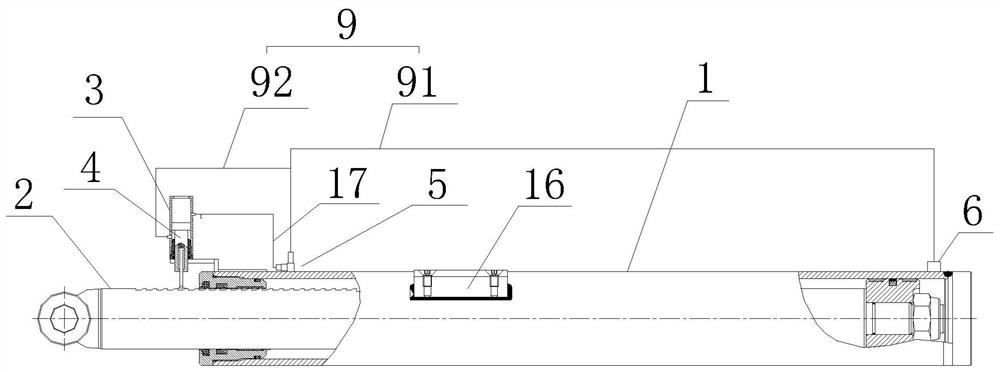
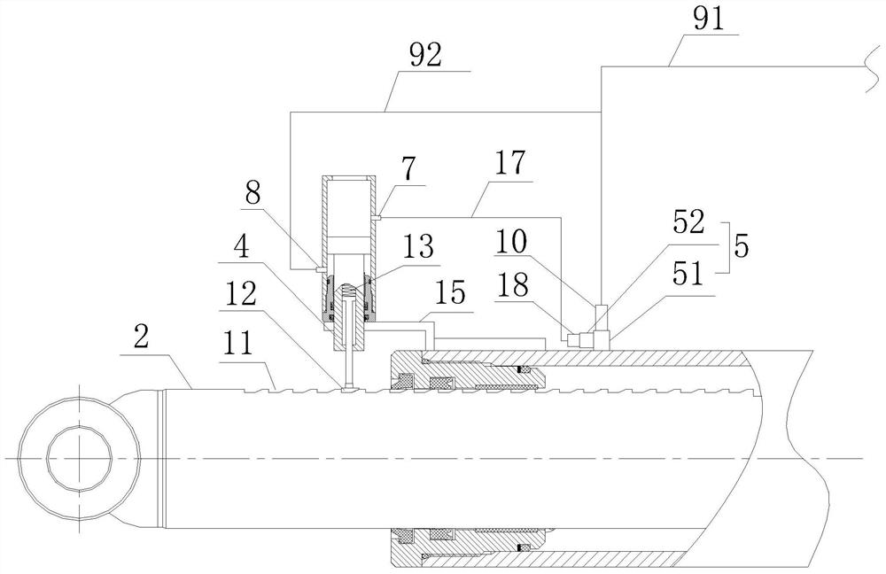
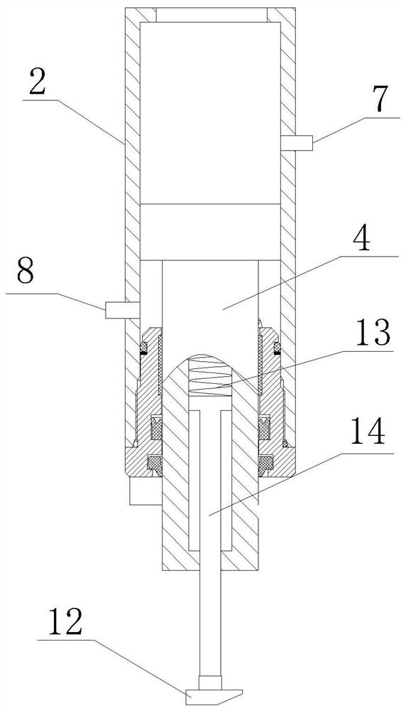
[0023] refer to Figure 1-3 , a jacking self-locking hydraulic cylinder proposed by the present invention, comprising: a master cylinder 1 with an oil port A5 and an oil port B6 and a first piston assembly installed in the master cylinder 1, with an oil port C7, The auxiliary cylinder 3 of the oil port D8 and the second piston assembly installed in the auxiliary cylinder 3, as well as the oil passage 9 for delivering hydraulic oil, the first piston assembly includes the first piston assembly located between the oil port A5 and the oil port B A piston and a first piston rod 2 connected with the first piston, the second piston assembly includes a second piston located on the side of the oil port D8 close to the oil port C7 and a second piston rod 4 connected with the second piston, and the first One end of the piston rod 2 is located outside the main cylinder 1 to form a first ejection end, and one end of the second piston rod 4 is located outside the auxiliary cylinder 3 to for...


PUM


Abstract

The invention provides a jacking self-locking hydraulic cylinder. The jacking self-locking hydraulic cylinder comprises a main cylinder barrel, a first piston assembly, an auxiliary cylinder barrel, a second piston assembly and an oil way, wherein the main cylinder barrel is provided with an oil port A and an oil port B, and the auxiliary cylinder barrel is provided with an oil port C and an oil port D; the first piston assembly comprises a first piston and a first piston rod, and the second piston assembly comprises a second piston and a second piston rod; the auxiliary cylinder barrel is located on one side of a first ejection end and fixed to the main cylinder barrel; the auxiliary cylinder barrel is further provided with an air port; the first piston rod is provided with locking grooves; the second piston rod is provided with a locking block elastically connected with the second piston rod, and the locking block is located in one locking groove; the oil port A comprises a main oil port and an auxiliary oil port; the oil port C is connected with the auxiliary oil port through a pipeline (17), and a first one-way valve is arranged between the oil port C and the auxiliary oil port; and the oil way comprises a main oil way connecting the main oil port and the oil port B and a branch connecting the oil port D and the main oil way, and a second one-way valve is arranged at the joint of the main oil port and the main oil way. According to the jacking self-locking hydraulic cylinder, self-locking can be achieved without manually moving a bolt or a cushion block.

Description

technical field [0001] The invention relates to the technical field of hydraulic cylinders, in particular to a jacking self-locking hydraulic cylinder. Background technique [0002] Self-locking hydraulic cylinders have a wide demand in engineering fields, such as in metallurgy, coal mines, construction machinery, sanitation vehicles and other mechanical fields of lifting and landing equipment. In order to prevent the workpiece from external force or self-weight (hydraulic pressure) when it stops working, hydraulic components The displacement occurs under the action of vertical cylinder), and the hydraulic cylinder needs to be locked. At present, there are mainly several methods for locking the piston rod of the hydraulic cylinder: one is to use a hydraulic lock in the hydraulic system to prevent the flow of hydraulic oil to lock the piston rod of the hydraulic cylinder; this locking method has obvious disadvantages: The internal leakage of the cylinder and the hydraulic lo...

Claims


Application Information

Patent Timeline
Patent Type & Authority Applications(China)
IPC IPC(8): F15B15/26F15B15/14F15B15/20
CPCF15B15/261F15B15/14F15B15/149F15B15/1457F15B15/20F15B2015/268
Inventor 钱昌雲
Owner 大大科技(宁国)有限公司
Learn More