Position visualization method of supporting structure of engineering machinery and engineering machinery

A supporting structure and construction machinery technology, which is applied to mechanically driven excavators/dredgers, earth movers/shovels, measuring devices, etc., can solve the problem of not being able to display bulldozing blades and outriggers in real time, and achieve convenience Position control, the effect of avoiding misoperation

Active Publication Date: 2021-10-29
SANY HEAVY MACHINERY
View PDF15 Cites 0 Cited by
  • Summary
  • Abstract
  • Description
  • Claims
  • Application Information

AI Technical Summary

Problems solved by technology

[0003] Therefore, the technical problem to be solved by the present invention is to overcome the defect that the wheeled excavator in the prior art cannot display the position of the bulldozing blade and the outrigger in real time, thereby providing a method for visualizing the position of the support structure of the construction machine and the construction machine

Method used


Image

  • Position visualization method of supporting structure of engineering machinery and engineering machinery
  • Position visualization method of supporting structure of engineering machinery and engineering machinery
  • Position visualization method of supporting structure of engineering machinery and engineering machinery

Examples


Embodiment Construction

[0025] The technical solutions of the present invention will be clearly and completely described below in conjunction with the accompanying drawings. Apparently, the described embodiments are part of the embodiments of the present invention, but not all of them. Based on the embodiments of the present invention, all other embodiments obtained by persons of ordinary skill in the art without making creative efforts belong to the protection scope of the present invention.

[0026] In the description of the present invention, it should be noted that the terms "center", "upper", "lower", "left", "right", "vertical", "horizontal", "inner", "outer" etc. The indicated orientation or positional relationship is based on the orientation or positional relationship shown in the drawings, and is only for the convenience of describing the present invention and simplifying the description, rather than indicating or implying that the referred device or element must have a specific orientation, ...


PUM


Abstract

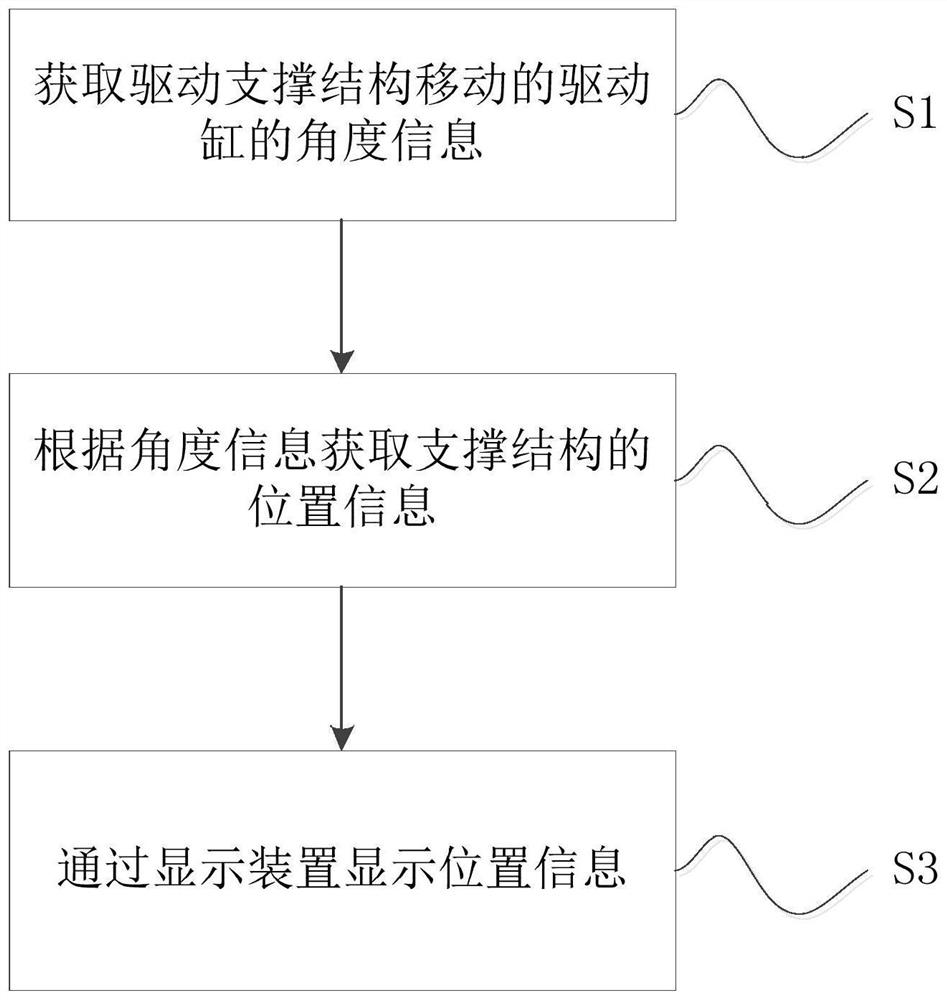
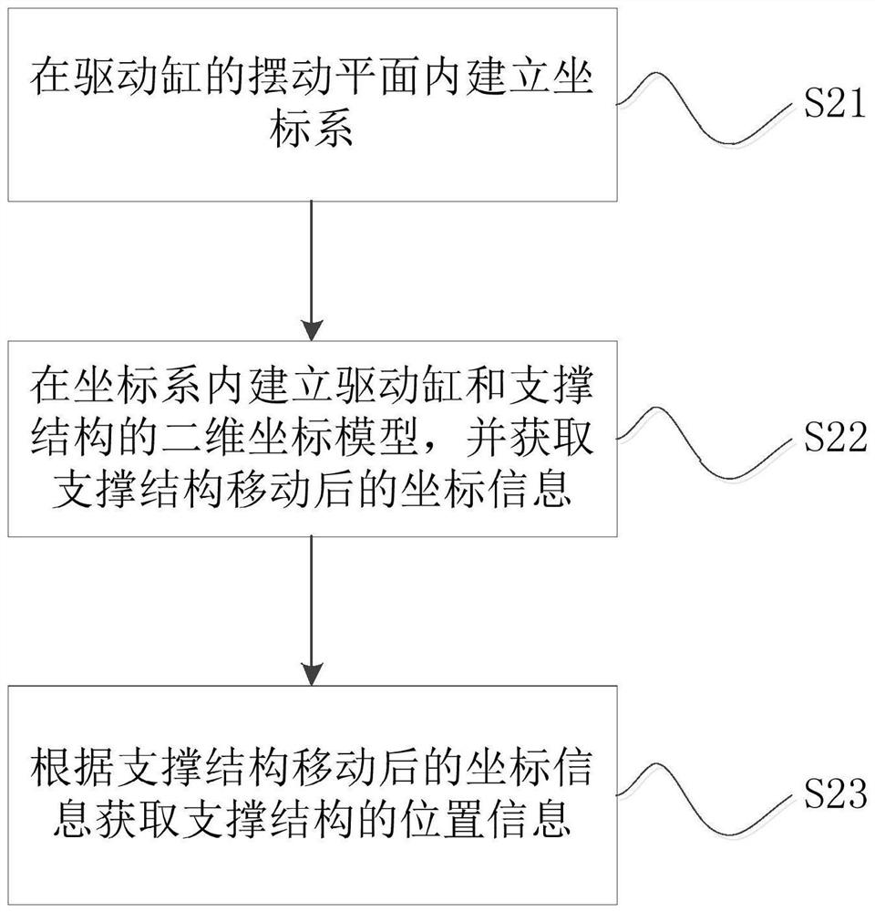
The invention provides a position visualization method of a supporting structure of engineering machinery and the engineering machinery. The position visualization method of the supporting structure of the engineering machinery comprises the steps: S1, obtaining the angle information of a driving cylinder for driving a supporting structure to move; S2, obtaining position information of the supporting structure according to the angle information; and S3, displaying the position information through a display device. According to the method, the position information of the supporting structure is obtained by obtaining the angle information of the driving cylinder for driving the supporting structure to move, and the position information is displayed on the display device; and according to the technical scheme, the position of the supporting structure can be displayed in real time, the defect that in the prior art, a wheel excavator cannot display the positions of the dozer blade and the supporting legs in real time is overcome, a driver can conveniently control the position of the supporting structure, and misoperation of the driver is avoided.

Description

technical field [0001] The invention relates to the technical field of engineering machinery, in particular to a method for visualizing the position of a supporting structure of an engineering machinery and an engineering machinery. Background technique [0002] At present, wheeled excavators are equipped with bulldozing blades and outriggers. When the wheeled excavator needs to perform operations, the bulldozing blades and outriggers are lowered and supported on the ground. At this time, the wheels of the wheeled excavator are off the ground. Thereby ensuring that the wheeled excavator is in a stable state. In the prior art, the lifting state of the bulldozing blade and the outrigger of the wheeled excavator depends on whether the driver perceives that the machine is in a state of holding pressure to determine whether the two have reached the limit state. The above-mentioned judgment method is easy to cause the driver to misuse. Contents of the invention [0003] Therefo...

Claims


Application Information

Patent Timeline
Patent Type & Authority Applications(China)
IPC IPC(8): G01B21/00E02F3/43E02F9/22E02F9/26
CPCG01B21/00E02F9/26E02F9/264E02F9/22E02F3/435
Inventor 陈炳文李春德杨赋
Owner SANY HEAVY MACHINERY
Why Eureka
Try Eureka