A Physical Load Photovoltaic Module Testing Equipment

A technology for photovoltaic modules and testing equipment, applied in the testing of machine/structural components, impact testing, measuring devices, etc., can solve problems such as troublesome and inconvenient operation, and achieve the effect of reducing consumption, reducing drop loss, and facilitating collection and recycling.

Active Publication Date: 2021-11-26
JIANGSU LINYANG PHOTOVOLTAIC TECH
View PDF1 Cites 0 Cited by
  • Summary
  • Abstract
  • Description
  • Claims
  • Application Information

AI Technical Summary

Problems solved by technology

[0005] The purpose of the present invention is to provide a physical load photovoltaic module testing equipment to solve the problem in the above background technology that in order to facilitate the disassembly and replacement of photovoltaic panels, it is necessary to manually switch the ice particle blocking mechanism frequently, and the operation is troublesome and inconvenient.

Method used


Image

  • A Physical Load Photovoltaic Module Testing Equipment
  • A Physical Load Photovoltaic Module Testing Equipment
  • A Physical Load Photovoltaic Module Testing Equipment

Examples


Embodiment 1

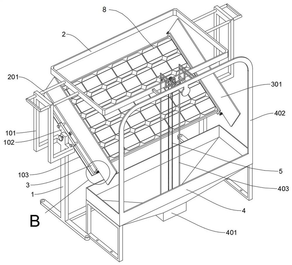
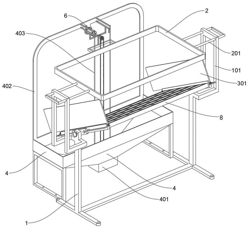
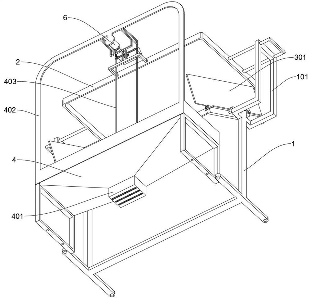
[0028] see Figure 1 to Figure 9 , Embodiment 1 provided by the present invention: a physical load photovoltaic module testing equipment, including a support 1; Commonly welded, wherein the tops of the left and right vertical braces are symmetrically welded with two vertical braces 101, and a rectangular blanking tray 2 is slidably installed between the top braces of the two vertical braces 101, and the left and right vertical braces There are two inclined mounting plates 102 symmetrically welded on the inner side of the top of the top, and two clamping parts 3 are mounted on the two inclined mounting plates 102 to push forward and symmetrically slide. There are three leaking tanks, and the three long leaking tanks are covered with metal screens;

[0029]The unloading tray 2 includes sliding shafts 201. The bottom opening of the unloading tray 2 is covered with a metal screen, and the left and right sides of the unloading tray 2 are symmetrically welded with four sliding shaf...


PUM


Abstract

The invention discloses a physical load photovoltaic component testing equipment, relates to the technical field of photovoltaic testing equipment, and solves the problem that in the existing testing equipment, in order to facilitate the disassembly and replacement of photovoltaic panels, it is necessary to switch and switch the ice particle blocking mechanism manually and frequently. The operation is troublesome and inconvenient. A physical load photovoltaic module testing equipment, including a bracket; the bracket includes a vertical support frame and an inclined installation plate, and the whole bracket is composed of left and right vertical support rods and bottom I-shaped ground contact seats welded together, wherein the left and right vertical support rods Two vertical bracing frames are welded symmetrically at the top, and a rectangular lowering tray is slidably installed between the top bracing plates of the two vertical bracing frames, and two inclined mounting plates are welded symmetrically on the inside of the top of the left and right vertical bracing bars. The blocking frame of the present invention can block the ice particles flying forward from the photovoltaic panel, which can further reduce the falling loss of the ice particles when used together with the shutter, and facilitate subsequent collection and recycling.

Description

technical field [0001] The invention relates to the technical field of photovoltaic testing equipment, in particular to a physical load photovoltaic module testing equipment. Background technique [0002] Photovoltaic panels are mostly installed outdoors. The use characteristics of outdoor installations determine that they should have the ability to deal with severe disaster weather, including anti-hail performance, and then a photovoltaic module testing equipment will be used to test the impact of hail. The impact physical load on the photovoltaic panel is tested. [0003] For example, patent No. CN201911206155.X discloses an anti-shock detection device for solar photovoltaic panels, including a base plate, T-shaped chute openings on the opposite sides of the top and outer walls of the base plate, and the sliding connection in the T-shaped chute has specifications. Compatible with the slider, the top outer wall of the slider is welded with support rods, and the top outer w...

Claims


Application Information

Patent Timeline
Patent Type & Authority Patents(China)
IPC IPC(8): G01M7/08
CPCG01M7/08
Inventor 裴骏汤海美陈景
Owner JIANGSU LINYANG PHOTOVOLTAIC TECH
Why Eureka
Try Eureka