
Antenna pedestal capable of receiving signals at multiple angles for vehicle networking communication

A signal receiving and multi-angle technology, which is applied to antennas, antennas, antenna supports/mounting devices suitable for movable objects, can solve the problems of multi-directional signal reception and difficult reception, and achieve signal stability, The effect of increasing the signal reception range

Pending Publication Date: 2021-10-29
张席
View PDF0 Cites 0 Cited by
  • Summary
  • Abstract
  • Description
  • Claims
  • Application Information

AI Technical Summary

Problems solved by technology

[0004] The purpose of the present invention is to provide a kind of multi-angle receiving signal suitable for Internet of Vehicles communication which can receive signals from different directions, can receive signals around the car from multiple angles, and can ensure signal stability, so as to solve the above-mentioned background The existing antenna base proposed in the technology cannot receive multi-directional signals, and it is difficult to accurately and quickly receive signals around the car

Method used


Image

  • Antenna pedestal capable of receiving signals at multiple angles for vehicle networking communication
  • Antenna pedestal capable of receiving signals at multiple angles for vehicle networking communication
  • Antenna pedestal capable of receiving signals at multiple angles for vehicle networking communication

Examples


Embodiment 1

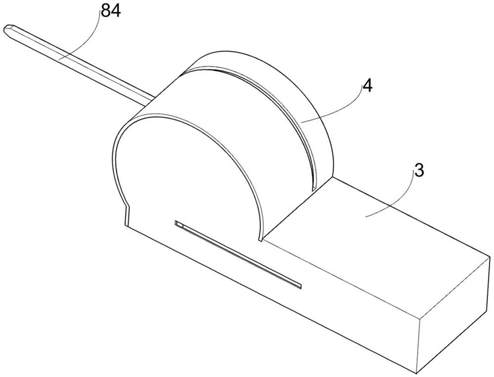
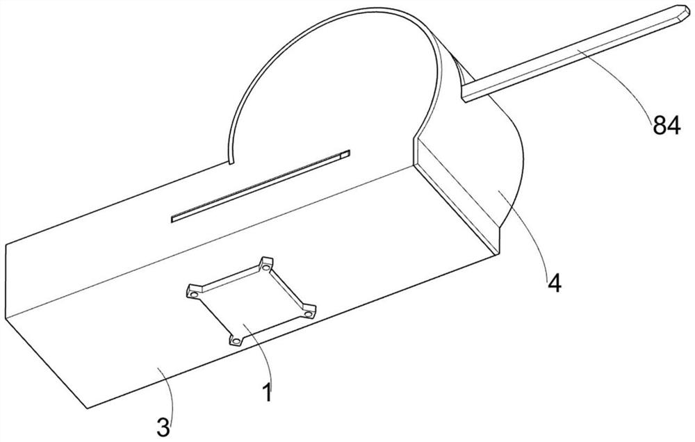
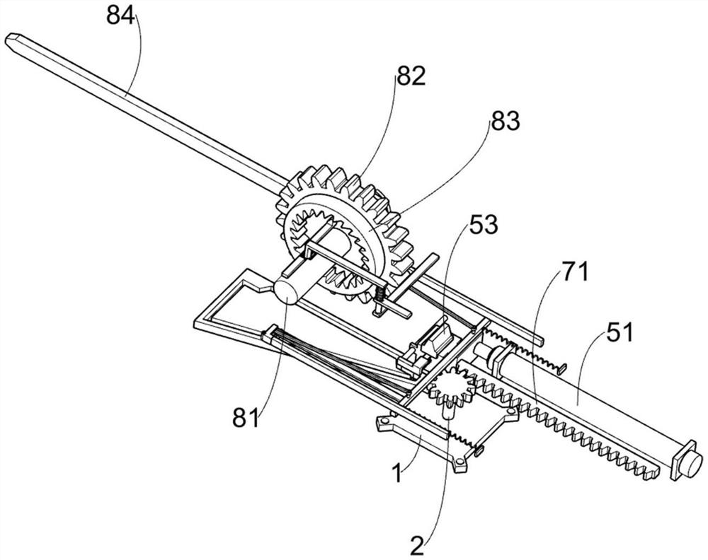
[0030] An antenna pedestal suitable for multi-angle receiving signals for Internet of Vehicles communication, such as Figure 1-10 As shown, it includes a threaded base 1, a rotating shaft 2, a mounting frame 3, an arc panel 4, a one-way drive mechanism 5, a one-way assembly 6, a rotation assembly 7, a first signal receiving assembly 8, a limit assembly 9 and a push-off Assembly 10, threaded base 1 is rotatably connected with rotating shaft 2, on which rotating shaft 2 is welded with installation frame 3, on which installation frame 3 is fixedly installed arc panel 4, inside installation frame 3 is fixedly installed with one-way drive mechanism 5, single The direction assembly 6 is arranged at the bottom of the installation frame 3, and the rotation assembly 7 used to make the equipment receive multi-directional signals is arranged on the one-way drive mechanism 5, and the installation frame 3 is rotatably connected with the first signal receiving assembly for receiving signals...

Embodiment 2

[0042] On the basis of Example 1, such as Figure 10 As shown, it also includes a second signal receiving assembly 11, the second signal receiving assembly 11 is arranged on the installation frame 3, the second signal receiving assembly 11 is used to enhance the signal, the second signal receiving assembly 11 includes a movable bar 111, a push Bar 112, fixed plate 113, back-moving spring 114, swing seat 115, second signal receiving rod 116 and connecting rod 117, sliding type is connected with movable bar 111 on the installation frame 3, and movable bar 111 one side is welded with push bar 112, installs A fixed plate 113 is symmetrically welded in the frame 3, and a return spring 114 is connected on the fixed plate 113. One end of the return spring 114 away from the fixed plate 113 is connected with the movable bar 111, and two swing seats 115 are connected in rotation on the installation frame 3, and the swing seat 115 is welded with a second signal receiving rod 116, the sec...


PUM


Abstract

The invention relates to an antenna pedestal, in particular to an antenna pedestal capable of receiving signals at multiple angles for vehicle networking communication, which comprises a threaded base, a rotating shaft, a mounting frame, an arc panel, a one-way driving mechanism and the like, wherein the rotating shaft is rotationally connected to the threaded base, the mounting frame is welded to the rotating shaft, the arc panel is fixedly mounted on the mounting frame, and the one-way driving mechanism is fixedly mounted in the mounting frame. Under the action of a chute guide plate, a guide rod and a device on the guide rod move towards the direction close to an electric push rod, a tooth block is meshed with an adjusting gear, the tooth block pushes the adjusting gear and the device on the adjusting gear to rotate clockwise, a first signal receiving rod swings upwards, the position of the first signal receiving rod is adjusted, and the purpose of receiving signals at different angles is achieved.

Description

technical field [0001] The invention relates to an antenna base, in particular to an antenna base suitable for multi-angle signal reception for vehicle network communication. Background technique [0002] The antenna pedestal is a device for supporting and positioning the antenna. The antenna pedestal makes the antenna move according to a predetermined rule through the antenna control system, or follows the target movement, accurately points to the target, and accurately measures the direction of the target through the axial position detection device. The antenna There are various types of mounts, which can be classified in many ways. According to the use environment, they can be divided into land use, marine use, and air use antenna mounts. Land use antenna mounts can also be divided into fixed type and vehicle-mounted type. [0003] The existing vehicle-mounted antenna base structure is relatively simple, the antenna is fixed in direction, and cannot move autonomously, so ...

Claims


Application Information

Patent Timeline
Patent Type & Authority Applications(China)
IPC IPC(8): H01Q1/12H01Q1/20H01Q3/02H01Q1/32
CPCH01Q1/12H01Q1/20H01Q3/02H01Q1/32
Inventor 张席
Owner 张席
Learn More