Nasal septum nail fixing device and nasal septum nail fixing system

A nasal septum and staple fixing technology, which is applied in the field of medical devices, can solve the problems of inability to judge the number of staples in the staple box, increase pollution, waste resources, etc., and achieve the effects of reducing postoperative complications, reducing edema, and saving time

Pending Publication Date: 2021-11-02
HEFEI BREATH MEDICAL CO LTD
9 Cites 1 Cited by

AI-Extracted Technical Summary

Problems solved by technology

However, the structure of this patent cannot determine the number of staples in the nail box; and the fixing method of the nail box may have the risk of the nail box falling, and it is not easy to replace
At present, the country strongly advocates the...

Method used

In some embodiments of the present invention, with reference to Fig. 2-8, described nail box push rod 121 is movably arranged on the main housing 1 of described nail fixer, and the side wall of described nail box push rod 121 is provided with sliding slot, the ejector rod 111 is movably arranged in the chute, the nail cartridge push rod 121 and the ejector rod 111 pass through the first through hole structure 14 and extend into the first implantation mechanism, It is beneficial to structural integration, so that the overall structure of the nail fixer is compact, and the overall volume of the main shell of the nail fixer is reduced.
In some embodiments of the present invention, with reference to Fig. 3, Fig. 7 and Fig. 8, the connecting end 123 that described nail box push rod 121 is connected with described nail box 5 is provided with external thread, the inner wall of described nail box 5 An internal thread adapted to the external thread is provided, and the connecting end 123 of the nail box 5 and the nail box push rod 121 is threadedly connected, so that the nail box is fixed more firmly and stably, and can effectively prevent the nail box from falling off. drop, and easy to replace.
In some embodiments of the present invention, with reference to Fig. 3-9, ejector rod 111, spring 112 and ejector block 113 constitute described ejection system, and one end of described spring 112 abuts against fixture (not shown in the figure ), the other end of the spring 112 abuts against one end of the push rod 111, one end of the top block 113 abuts against the other end of the push rod 111, and the other end of the top block 113 passes through the first A through hole structure 14 protrudes into the first implant mechanism 2 to resist the staple set 4, so that the staple set 4 discharges a staple, which can be pushed by the elastic force of the spring 112. The ejector rod 111 and the ejector block 113 automatically push the staple group 4 to move toward the staple output end of the first implant mechanism 2, fully automatic control, simple and convenient, and help to ensure the smooth discharge of the staples sex. In some specific embodiments of the present invention, the fixing member includes a spring chamber 114, the spring 112 is movably arranged in the spring chamber 114, and one end is abutted against the bottom of the spring chamber 114, so that the spring 112 can realize shrinkage and extension between the bottom of the spring chamber 114 and the push rod 111 .
In some embodiments of the present invention, with reference to Fig. 7-9, described track top plate 154 is arranged on an open end of described nail box support 153, and described track top plate 154 and described nail box support 153 are detachable connection for easy cartridge replacement.
In some embodiments of the present invention, with reference to Fig. 8 and Fig. 9, described first implant mechanism 2 comprises implant support 21, described implant support 21, described pulling wire fixing plate 172 and described nail box The brackets 153 are all cavity structures, the traction ...

Abstract

The invention provides a nasal septum nail fixing device. The nasal septum nail fixing device comprises an implantation system, a driving system and an ejection system; the implantation system comprises a first implanting mechanism and a second implanting mechanism, the driving mechanism comprises a braking mechanism, a clamping driving mechanism and a nail discharging driving mechanism, and the braking mechanism drives the clamping driving mechanism to drive the second implanting mechanism to move towards or away from the first implanting mechanism; the braking mechanism drives the nail discharge driving mechanism to discharge a suturing nail from the first implanting mechanism so as to realize rapid suturing; one end of the ejection system abuts against the suturing nail set, and after the suturing nails are discharged from the first implanting mechanism, the ejection system drives the suturing nail set to move towards the nail outlet end of the first implanting mechanism, so that the implanting direction of the next suturing nail can be adjusted by adjusting the positions of the first implanting mechanism and the second implanting mechanism. And the purpose of accurately implanting the suturing nail is achieved. The invention further provides a nasal septum nail fixing system.

Application Domain

Surgical staples

Technology Topic

EngineeringBiomedical engineering +3

Image

  • Nasal septum nail fixing device and nasal septum nail fixing system
  • Nasal septum nail fixing device and nasal septum nail fixing system
  • Nasal septum nail fixing device and nasal septum nail fixing system

Examples

  • Experimental program(1)

Example Embodiment

[0051] In order to make the objects, technical solutions, and advantages of the present invention, the technical solutions in the embodiments of the present invention will be clear and completely described, as will be described, and it is understood that the described embodiments are the embodiments of the present invention, not all Embodiments. Based on the embodiments in the present invention, all other embodiments obtained without creative labor are not made in the premise of creative labor. Unless otherwise defined, the technical term or scientific terminology used herein should be understood to have a common meaning of people who have general skills in the art of the present invention. Similar words to "include" as used herein mean that the elements or objects of the previous appearance of the word or objects are enumerated in the following words and their equivalents, without excluding other elements or objects.
[0052] To overcome the problems in the prior art, embodiments of the present invention provide a predetermined nasal septum staple comprising implant system, ejection system and a drive system;
[0053] The implant system comprises a first implant and the second implant mechanism means, said first implant and said second implant mechanism means disposed opposite said first implant and said second implant mechanism separator means arranged to receive a septum of a patient;
[0054] The drive mechanism includes a braking mechanism, clamp driving mechanism and a staple discharge driving means, said brake means respectively connected to said discharge driving means and said clamping nail driving mechanism, the drive mechanism and the clamping means connecting the second implant, said brake driving mechanism to drive the clamping mechanism drive means toward said second implant or implant away from the first movement mechanism, the staple driving mechanism and the second discharge means connected to an implant, said brake mechanism to drive the staple driving mechanism to discharge exhaust from the first implant staple mechanism;
[0055] One end of the ejector system abutting staples group, after the first implantation of the staple mechanism is discharged out of the system drives the top end of the movement of the staple of the staple toward the first set of implant mechanism.
[0056] Septum staple mechanism is given every time when the brake mechanism is triggered, only one staple is implanted wound, and the next staple in the magazine are pushed to the first implant means end of the nail; when more staple implantation, the brake mechanism is triggered, the implant a staple again.
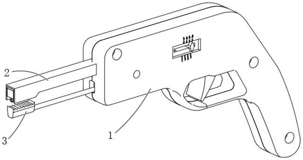
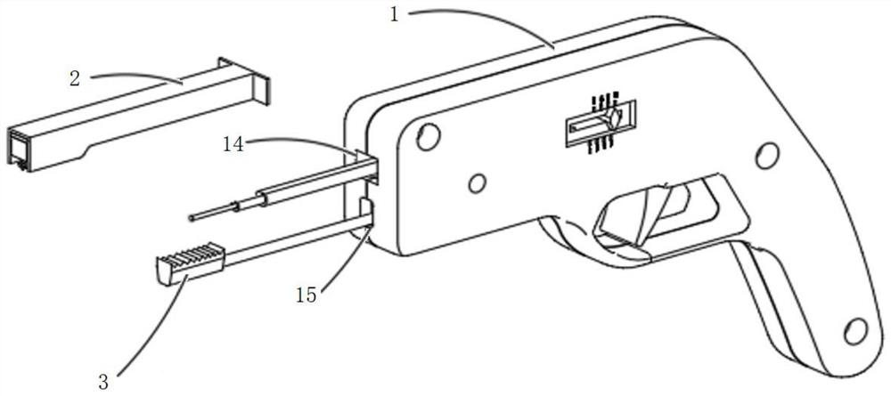
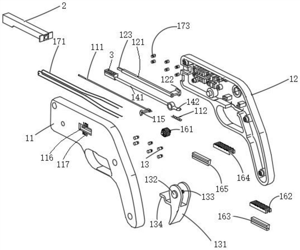
[0057] figure 1 Nasal given configuration diagram of an embodiment of a staple of the present invention; figure 2 For figure 1 Septum given structure shown in schematic form a portion of the staple configuration after decomposition; image 3 Septum exploded view of the staple set according to an embodiment of the present invention.
[0058] Some embodiments of the present invention, with reference to figure 1 , figure 2 with image 3 The set includes a staple main body 1, a first implant and the second implant mechanism 2 means 3, the main housing 11 includes a first housing 12 and second housing, said first housing 11 and the second housing 12 is fixedly connected. Some specific embodiments of the present invention, the main housing 1 has a pistol-shaped structure.
[0059] Some specific embodiments of the invention, the reference image 3 The first housing 11 and second housing 12 are connected by screws 13 is fixed.
[0060]Other embodiments of the present invention, the first housing 11 and 12 by snap riveting or the second embodiment DETAILED DESCRIPTION like housing fixedly connected.
[0061] Some embodiments of the present invention, with reference to figure 1 with figure 2 The main body 1 comprises a second through hole 14 and a through-hole structure of the first structure 15, the first implant mechanism 2 and the fixed staple main housing 1 is fixedly connected, and the first implant means 2 into the open end 14 communicates with the first through-hole mating structure. Some particular embodiments of the present invention, the structure of the first through hole 14 and the second through holes 15 spaced apart from the structure, in order to avoid passing through the first through hole 14 and the structure of the second through hole 15 of the structure impact member collide with each other using friction.
[0062] Figure 4 Schematic right side view of the present invention, the internal structure of the nasal septum given embodiment of the staple; Figure 5 The internal structure of a given septum staple according schematic left side view of the embodiment of the present invention; Image 6 Set septum staple embodiment of the present invention assembled in a schematic view of the right drive mechanism; Figure 7 Schematic view of an assembly of a left nasal given embodiment of the staple drive mechanism embodiment of the invention; Figure 8 Mounting a schematic internal configuration of a first predetermined nasal septum implanted staple mechanism of the present invention in an embodiment; Figure 9 A first exploded view of an internal structure of a given implant means septum staple embodiment of the present invention.
[0063] Some embodiments of the present invention, with reference to Figure 3-9 , Plunger 111, spring 112 and the top of the block 113 constituting the ejector system, one end of the spring 112 abuts a fixed member (not shown), the other end of spring 112 abuts the plunger end 111, 113 of the top block end abuts the other end 111 of the jack, the other end of the top block 113 through the first through hole 14 and extending into said first structure means implant 2, resisting the staple group 4 to group 4 such that the staple discharge a staple, with the spring force can 112 is automatically pushed by the pushing jack 111 and the top of the block 113 movement of the ends of the staple 4 to the staple implantation mechanism 2 first set, automatic control, easy, helps ensure the smooth discharge of the staples. Some specific embodiments of the present invention, the fixing member comprises a spring chamber 114, the spring 112 is movably disposed within the spring chamber 114, and one end of said spring chamber abutting the bottom portion 114, so that the spring 112 can be at the bottom of the spring chamber 114 and the jack 111 between contraction and elongation achieved.
[0064] Some embodiments of the present invention, with reference to image 3 , Figure 5 , Figure 6-8 , And the numbers indicate the pointer structure 115 constitutes part of the ejector system, the digital indicator comprises a plurality of digital pointer is moved through the main housing 116 and the receiving window arranged in an outer wall of the main body 1 of the reference 117, a pointer to the structure 115 and the jack 111 vertically disposed, the pointer structure 115 through the receiving window movement of the pointer 116 and the pointer structure 115 with the plunger 111 and movement of the pointer in window moving toward the housing 116 and the digital reference point 117, i.e., the use of reference numbers provided on the main housing 117 to indicate the number of staples discharged, simple, easy to know clearly the number of staple implantation. Some embodiments of the present invention, the movement of the pointer 116 and the receiving window of a plurality of digital reference numeral 117 is provided to the first housing 11.
[0065] Specifically, the digital reference sequence like 1,2,3,4 digit from the implant means away from the first direction to close said first implant means are arranged in ascending order, the first implant a staple discharging mechanism, the pointer structure with the ram movement of a moving window housed in a frame in the forward movement of the pointer, the digital reference pointer structure indicated changes. For example: the original digital reference pointer structure is indicated 2, the first implant a staple ejection mechanism, with the structure of the pointer movement of the plunger forward movement of the receiving window pointer movement a grid, the reference numbers indicating pointer structure 3 is changed to indicate that the exhausted three staples.
[0066] Some embodiments of the present invention, the septum further comprising a fixed staple staple cartridge and the staple cartridge assembly Alternatively, the reference Figure 3-9 The magazine 5 is provided on the first implant containing means 2 to 4 groups of the staple, the staple cartridge replacement assembly comprising a push handle receiving window move pusher 121 and the staple cartridge, accommodating the push handle to move a window through said main casing 1 is given the staple, the staple cartridge pusher 121 is provided at one end with a vertical push handle 122, the other end of the staple cartridge pusher 121 through the first through hole 14 and the structure extends into the connector 25 in the first implant and the staple cartridge means, the push handle through the push handle 122 toward the housing window and the push handle is movable toward the housing window; i.e. by pushing the push handle 122 to move the push handle receiving window movement, so as to drive the staple cartridge pusher 121 toward the first direction implant mechanism 2, to the staple cartridge 5 from the first implant Release of the mechanism 2, in order to achieve the replacement magazine 5.
[0067] Some embodiments of the present invention, the push handle to move the receiving window disposed in said second housing.
[0068] Some embodiments of the present invention, with reference to image 3 , Figure 7 with Figure 8 , Connecting end 123 of the staple cartridge and the staple cartridge pusher 121 is provided with an external thread 5 is connected, the inner wall of the magazine 5 is provided with an internal thread adapted to the external thread, and the magazine 5 the staple cartridge pusher 121 is connected to end 123 by a threaded connection mode, such that the staple cartridge is fixed more firmly stable and can effectively prevent the magazine from falling, and easy to replace.
[0069] Some embodiments of the present invention, with reference to Figure 2-8 , The staple cartridge pusher 121 is movably disposed within the main housing is given a staple, the staple cartridge pusher 121 is provided with a side wall chute, the chute of the plunger 111 is movably disposed, the staple cartridge pusher 121 and the plunger 111 through the first through-hole structures extending into said first implant 14 and mechanism conducive structurally integrated, so that the overall configuration of a staple compact set, Save small overall volume of the main housing of the staple set.
[0070] Some embodiments of the present invention, the brake mechanism comprises a brake lever and brake assembly, the reference Figure 3-8 The brake assembly includes a trigger 131 and a connecting shaft 132, the trigger 131 is provided with slots 133 and the through-hole structure, the connecting shaft 132 is fixed through the through hole provided in the structure, the trigger 131 and the fixedly connected to the brake lever 134, the trigger 131 is movably mounted to the main body case 1, a user can use as a pistol or releasing the trigger 131 is pulled to effect ejection of staples. Some embodiments of the present invention, the trigger lever 131 and the brake 134 is a unitary structure.
[0071] Some embodiments of the present invention, with reference to Figure 3-8 The clamping mechanism comprising a driven drive rod 141, the driven lever 141 is movably disposed within the main housing 1, one end portion of the driven lever 141 is a brake 142, the brake lever the driven lever 134 and the brake portion 142 of the lap 141, the other end of the driven shaft 141 through the second through-hole 3 and the connecting structure 15 is fixed to the second implant means, by the brake assembly to drive the rotation of the lever 134 presses the brake or releasing the brake portion 141 of the driven lever 142, so that the driven lever and the other end portion 141 of the second drive embedding unit 3 toward or away from the first implant movement mechanism 2, so that the second implant 2 and 3 means implementing the first implant or clamping means separated. Specifically, by artificially pulling the trigger 131, while allowed to pivot by the rotation of the shaft 132 that is rotatably connected to the brake lever 134 in contact with the brake lever 141, the driven portion 142, so that the other end portion of the driven shaft 141 of the drive mechanism 3 toward the first implant and the second implant movement mechanism 2, so as to achieve the purpose of clamping the soft tissue and nasal mucosa; relax by artificially press the trigger 131 At the same time, passed through a rotational fulcrum shaft 132 that is connected to the reverse rotation of the brake lever 134 driven lever 141 in the part 142 does not contact the brake, the other end portion of the driven shaft 141 and the drive means of the second implant 3 implanted mechanism 2 is moved away from the first, so as to achieve the purpose of releasing the soft tissue and nasal mucosa. The embodiment of the present embodiment is a lap 134 of the brake lever and the driven lever 141 each have a certain overlap.
[0072] Some embodiments of the present invention, the drive mechanism includes a staple ejection braking gear assembly, the drawing assembly and assembly of rows of staples, said brake assembly with the brake gear assembly connected to said traction assembly and said respective brake a gear assembly and the staple discharge assembly connected to drive the rotation of the braking gear assembly moved by said brake assembly, the brake assembly gear assembly drives the staple rows to the movement by said drawing assembly the staple is discharged from the first implant means in order to achieve discharging staples from the mechanism of the first implant.
[0073] Some embodiments of the present invention, the drawing assembly comprises a pull wire and a traction wire fixing assembly, both ends of the pull wire are fixed with the brake gear assembly, and the pull wire through the pull wire fixed to said fixed assembly forming an annular structure, to achieve the cycle was repeated many times to drive the movement of the assembly rows of staples of the staple discharged from the first implantation mechanism.
[0074] Figure 10 Fitting a schematic view of a partial structure of the present invention, a given embodiment of the septum of the staple.
[0075] Some embodiments of the present invention, the exhaust assembly disposed in said first staple implanting means, the reference Figure 7-10 The assembly comprises a row of staple pushing plate 151, the track 152, the magazine holder 153, roof rail 154, the rail 152 is provided on the top of the bracket 153 of the staple cartridge, the staple track to the top plate 154 and the cartridge holder 153 connector 152 is formed in communication with the track rail, the push plate 151 is fixedly connected to the pull wire 171, the pull wire 171 to drive the push plate 151 is moved to the rail 152 and the rail, so that the push a head holding plate 151 abuts the staple of the staple discharged from the first implant of the mechanism, so that the braking mechanism each time the trigger, the pull wire 171 by driving the push plate 151 moving to launch a staple implanted wound.
[0076] Some embodiments of the present invention, with reference to Figure 7-9 The roof rail 154 is provided on an open end of the magazine holder 153, and the top plate 154 and the staple rail cartridge holder 153 is removably connected to facilitate the replacement of the staple cartridge.
[0077] Some embodiments of the present invention, the thickness of the push plate is less than or equal to the width of the stapling head of the nail, so that the braking device is triggered each time, only one staple is implanted wound, while in the magazine the next staple is pushed out of the system of the top of the first end of the implant means that the staples; when more staple suture braking mechanism is triggered again, the implanted an implant the staples, a plurality of individual staples are sequentially implanted, such that during closing septum without tearing. Embodiments of the present invention, the width of the stapling head of the nail is the maximum length of the staple head abuts against the head of the staple pushing plate and the direction perpendicular to the direction.
[0078] Some embodiments of the present invention, the braking gear assembly includes a brake gear, a first tooth and a second tooth bar assembly bar assembly, the brake assembly is connected with the brake gear, the first tooth bar assembly and said second assembly opposite rows of teeth disposed symmetrically at the end of the braking gear, one end of the pull wire with the first row of teeth fixed connector assembly, the other end of the traction wire and the second tooth the brake assembly through a gear assembly connected to a fixed row, so that the driving movement of the traction assembly, said rows of staples to effect drive movement assembly to discharge the staples from the mechanism of the first implant.
[0079]Specifically, reference Figure 3-7 The brake gear 161 via the connecting shaft 132 is disposed through the slot 133 is fixed to and rotates with the trigger 131 is rotated. The first assembly comprises a first row of teeth rows of teeth 162 and a first row of teeth fixing bracket 163, the second assembly comprising a second row of teeth 164 and a second row of teeth fixing bracket 165 rows of teeth, the first tooth row fixing bracket 163 and the second fixing bracket 165 is fixed rows of teeth disposed within the main housing 1, the first row of teeth of the first rows of teeth 162 and the fixing bracket 163 is fixedly connected to the second row of teeth row of teeth portion 164 is fixedly connected to the second fixing bracket 165 rows of teeth, the first tooth and the tooth 162 in a row and the second row of teeth 164 disposed opposite and symmetrical with the brake gear 161 are disposed abutting ends, one end of said traction wire 171 is connected to the first row of teeth 162 is fixed, the other end of the traction wire 171 is connected and fixed to the second row of teeth 164. Some particular embodiments of the present invention, the first row of teeth and the second fixing bracket 163 rows of teeth snap fixing bracket 165 by way of an inner wall of each of the first housing 11 and second housing 12 fixed connection. Specifically, the trigger 131 by the action of slots 133, 161 is connected with the brake gear, by artificially pulling the trigger 131, the brake gear 161 with the movement of the trigger 131 is rotated, so as to drive the first and second rows of teeth 162 moving rows of teeth 164 to drive the pull wire 171 and the wire 171 pulling the push plate 151 with the track 152 and the track 152 in communication a fixed rail trajectory, such that the action of the push plate 151 abutting the end of a predetermined position of the staple and the staple is pushed into the nasal cavity of the human body.
[0080] Some embodiments of the present invention, with reference to Figure 3-10 The pull wire assembly comprising a pull wire fixing plate 172 fixed sheave 173 and a plurality of pull wire, the pull wire 172 and the fixing plate 153 is connected and fixed staple cartridge holder and disposed within the first implant mechanism 2, the said pull wire fixing plate 172 and the end surface of the staple cartridge holder 153 is a symmetric pull wire is provided with a mounting groove 174, the wire traction sheave 173 disposed on an inner wall of the main casing 1 is given nail, the pulling a plurality of wire 171 through the wire traction sheave 173, the pull wire 172 and the fixing plate 153 is fixed to the staple cartridge holder form a ring structure. specifically, the pull wire 171 by sequentially disposed around said plurality of active dragline pulleys 173, 172 one end of said traction wire fixing plate mounting groove 174 of the pull wire, the pull wire staple cartridge mounting groove 153 of the end surface of a bracket 174, the end surface of the staple cartridge holder 153 further symmetrical mounting groove 174 dragline , 174, a plurality of pull wire 172 further traction sheave of the fixed plate symmetrically end surface dragline silk mounting groove 173 to form an annular structure.
[0081] Some embodiments of the present invention, with reference to Figure 8 with Figure 9 The mechanism 2 includes a first implant stent 21, the stent 21, the traction wire cavity structure 153 are fixed to the plate 172 and the staple cartridge holder, the fixing plate 172 and pull wire the magazine holder 153 is fixed to the implant of the cavity structure holder 21 in the staple cartridge holder 153 is detachably fixed to the magazine 5, the staple cartridge 5 that is disposed on the staple cartridge holder cavity structure 153, a structure conducive to integration, such that the overall structure of a given nail compact, reducing the overall volume of the first implant mechanism. Specifically, the staple cartridge pusher 121 through the fixing plate 172 and pull wire 5 is connected to the staple cartridge, the plunger 111 disposed within the staple cartridge pusher chute 121, and in turn wear through the pull wire 172 and the fixing plate 5 with the staple cartridge slidably disposed within the staple cartridge 113 in the top block 5 resisting.
[0082] Some specific embodiments of the invention, the reference Figure 10 The pull wire 172 and the fixing plate 153 is fixedly connected to the magazine holder by a snap manner.
[0083] Some embodiments of the present invention, with reference to Figure 9 The staple cartridge includes a staple cartridge receiving chamber 5 and the staple for staple sliding chute 51. Specifically, reference Figure 7 with Figure 8 , The staple and group 4 block 113 disposed on the top of the staple cartridge accommodating chamber, said pushing jack 111 through 113 set the staple ejector block 4 is moved in the slide groove 51 in the staple . The staple housed in the staple cartridge for nasal surgery, can effectively prevent accidental displacement of the nail head.
[0084] Some embodiments of the present invention, there is also provided a set screw system septum, the septum comprising a fixed staple and the staple, the staple disposed in said first septum implant the staple in a given mechanism.
[0085] Some embodiments of the present invention, the use of absorbable staple made of degradable material. Specifically, the degradable material includes a resorbable polyglycolic acid (PGA) or polylactide (PLA), polyglycolic acid or from (PGA) and polylactide (PLA) copolymer as ingredients. In order to improve the polylactide (PLA) degradation rate, polyglycolic acid (PGA) was added polylactide (PLA) to form copolymeric material can accelerate the degradation time of the liquid absorbing staples, thus speeding up the staple.
[0086] Some embodiments of the present invention, the staple comprises a staple body, and the driving portion and the nut portion are respectively provided at both ends of the nail body, the nut portion of the staple body arranged vertically, so that the staple by the unit can easily pass through the septum like implant tissues, and the like can be stably fixed nasal tissues and the like through the nut portion.
[0087] Some embodiments of the present invention, the staple is integrally formed structure.
[0088] Some embodiments of the present invention, the end surface of the push plate against the nut holding portion is provided with a groove, the push plate such that when the staple pushing movement, the push plate is capable of resisting the said recess push trough, there is the focal point, easier to promote.
[0089] Some embodiments of the present invention, the nut portion is any one of I-shaped configuration, a circular configuration and a cross-shaped structure, i.e., the upper surface of the nut portion of I-shaped configuration, a circular configuration and the cross any structure. Greater active surface area of ​​the nut and the nut portion of the cross section of the circular configuration of the large structure, such that the nut portion of the nasal septum like tissue fixed area, fixed more firmly. The I-shaped structure is a cylindrical structure or a rectangular parallelepiped-shaped configuration.
[0090] Some embodiments of the present invention, the driving portion is any one of a hook structure and a conical structure. The hook-shaped configuration of the driving unit for different tissue thicknesses and the like septum, greater versatility; the tapered configuration of the driving unit for smaller organizations such as the remaining area of ​​the scene septum, and the like when a small tissue area septum can be achieved effectively fixed.
[0091] Some embodiments of the present invention, the driving portion of the hook-shaped structure is provided with at least one hook, and the hook end is fixed to the acting end portion of the driving.
[0092] Figure 11 Schematic structural diagram of a first embodiment of the staple of the embodiment of the present invention.
[0093] Some specific embodiments of the invention, the reference Figure 8 with Figure 11 Said first staple 100 includes a first I-shaped nut portion 101, the hook portion 102 and the first nail driven into the body 103, the first I-shaped nut 101 and the hook portion 102 is provided in the driving portion the staple ends of the first body 103, the first I-shaped upper surface 101 of the nut portion provided with a groove 104, the groove 104 and the push plate 151 is adapted such that the push plate holding the can 151 against the recess 104 pushes the first staple 100 is moved, specifically, a first portion of I-shaped nut 101 has a rectangular parallelepiped-shaped configuration.
[0094] Figure 12 Schematic structural diagram of a second embodiment of the staple of the embodiment of the present invention.
[0095] Some specific embodiments of the invention, the reference Figure 12 A second staple 200 includes a second I-shaped nut portion 201, a first tapered portion 202 and the second nail driven into the body 203, the first 201 and the second I-shaped staple tapered nut portion into the portion 202 disposed at both ends of the second staple body 203, particularly, the I-shaped second portion 201 cylindrical nut structure.
[0096] Figure 13 Schematic structural diagram of a third embodiment of the staple of the embodiment of the present invention.
[0097] Some specific embodiments of the invention, the reference Figure 13 The staple 300 includes a circular third nut portion 301, a second tapered portion 302 and the third nail driven into the body 303, the circular portion of the nut 301 and the second tapered portion 302 is provided on the driving the third body ends 303 of the staple.
[0098] Figure 14 A schematic structural diagram of a fourth embodiment of the staple of the embodiment of the present invention.
[0099] Some specific embodiments of the invention, the reference Figure 14 The fourth cross-shaped staple 400 includes a first nut portion 401, a single hook portion 402 and the fourth nail driven into the body 403, the first cross-shaped nut portion 401 and the driving portion of the single hook 402 is provided to the fourth body ends 403 of the staple.
[0100] Figure 15 A schematic structural diagram of the embodiment of the staple of a fifth embodiment of the present invention.
[0101] Some specific embodiments of the invention, the reference Figure 15 The fifth staple 500 includes a second cross-shaped nut portion 501, four hook portions 502 and the fifth nail driven into the body 503, the second cross-shaped nut portion 501 and the driving of the four hook portions 502 acting provided at both ends of the fifth staple body 503, the hook-driving portion 502 includes four hook four, four and one end of the hook body hook fixed to the driving portion 502 of the four end .
[0102] Septum usually 2-4 mm thick, covered on both sides with a layer called the mucosa adhesive weeks periosteum, imagine a sandwich between two thin bread, sausage, bologna nasal septum, bread mucosa. Object of the nasal septum surgery is carefully mucous membrane on both sides of the diaphragm from dura elevation, partially offset removed, and then the clamp everything together, the treatment process prior nasal surgery as follows:
[0103] Step S1: The half-cut in the mucosal lining of the nasal septum side;
[0104] Step S2: Freer using captopril or riser, the mucous membrane of the dura is lifted from one side of the septal cartilage;
[0105] Step S3: immediately forward skew instrument manually cut septum, mucosal lining of the septum cartilage peeled off from the other side of the separator;
[0106] Step S4: The deviation of the nasal septum portion physically removed, can be removed with a chisel maxillary crest;
[0107] Step S5: the lapse of cartilage particles (such as hammer to remove the "memory") and replaced;
[0108] Step S6: using sutures or adhesive nasal packing bag will close again periosteum line.
[0109] If treatment with septum screw system according to the present invention is given in rhinoplasty (rhinoplasty Surgery, NRS) and endoscopic sinus surgery (EndoscopicSinus Surgery, ESS), the NRS usually after ESS. Using one kind of a given nail nasal treatment system, comprising the steps of:
[0110]Step S11: The disposable nail cartridge is placed in the nose, which is placed in the nose bracket of the nose, and connects the nail cartridge to the staple box to prevent the staples of the nail. Shift;
[0111] Step S12: The first implant mechanism and the second implant mechanism of the nose and the second implant mechanism are inserted into the two nostrils of the patient to receive the first implant mechanism and the second implant mechanism. The nasal septum is adjusted according to the position where the sewing is adjusted, ensuring that the nasal separation stapler is properly placed in effect.
[0112] Step S13: Prior to the formally discharge of the stitched nit, gently pull the trigger to give the first implant mechanism of the nose and the second implant mechanism and the second implant mechanism;
[0113] Step S14: Pull the trigger and then release it immediately, don't be too fast, don't be too slow, imagine the best effects of using ordinary bookers on a stack of paper;
[0114] Step S15: After the single implantation is implanted, the implantation direction of the next stitch is adjusted by adjusting the position of the first implant mechanism and the second implant mechanism, and the nasal separation nail is unfolded. Make sure that the nose is separated in the nose before the movement is released;
[0115] Among them, in order to ensure a suitable placement, each stitch must pass through at least two layers of the three tissue layers, including the right mucosa, septum, and left mucosa.
[0116] Although the embodiments of the present invention will be described in detail above, it will be apparent to those skilled in the art, and these embodiments can be made to various modifications and variations. However, it should be understood that such modifications and variations are within the scope and spirit of the invention described in the claims. Moreover, the invention described herein may have other embodiments, and can be implemented or implemented in a variety of ways.

PUM

no PUM

Description & Claims & Application Information

We can also present the details of the Description, Claims and Application information to help users get a comprehensive understanding of the technical details of the patent, such as background art, summary of invention, brief description of drawings, description of embodiments, and other original content. On the other hand, users can also determine the specific scope of protection of the technology through the list of claims; as well as understand the changes in the life cycle of the technology with the presentation of the patent timeline. Login to view more.

Similar technology patents

CT image-based lung lobe segmentation method and device

ActiveCN107392910Ashorten the time
Owner:SHENYANG NEUSOFT MEDICAL SYST CO LTD

Quick heating type heat pump water heater for recovering shower waste heat

ActiveCN102607170Ashorten the timeIncrease power and efficiency
Owner:佛山市三角洲电器科技有限公司 +1

Hotspot video displaying method and device

InactiveCN105872813Ashorten the time
Owner:LETV INFORMATION TECH BEIJING
Why Eureka
Try Eureka