
Electric box of injection molding machine

A technology for injection molding machines and electrical boxes, applied to electrical components, substation/power distribution device shells, substation/switch layout details, etc., can solve problems such as installation and maintenance inconvenience, and achieve the effect of solving maintenance inconvenience and ensuring safety

Pending Publication Date: 2021-11-02
BORCH MACHINERY
View PDF0 Cites 0 Cited by
  • Summary
  • Abstract
  • Description
  • Claims
  • Application Information

AI Technical Summary

Problems solved by technology

[0008] In order to overcome the deficiencies of the prior art, one of the objectives of the present invention is to provide an injection molding electromechanical box, which can solve the problem of inconvenient installation and maintenance

Method used


Image

  • Electric box of injection molding machine
  • Electric box of injection molding machine
  • Electric box of injection molding machine

Examples


Embodiment Construction

[0027] Below, the present invention will be further described in conjunction with the accompanying drawings and specific implementation methods. It should be noted that, under the premise of not conflicting, the various embodiments described below or the technical features can be combined arbitrarily to form new embodiments. .

[0028] It should be noted that when a component is said to be "fixed" to another component, it can be directly on the other component or there can also be an intervening component. When a component is said to be "connected" to another component, it may be directly connected to the other component or there may be intervening components at the same time. When a component is said to be "set on" another component, it may be set directly on the other component or there may be an intervening component at the same time. The terms "vertical," "horizontal," "left," "right," and similar expressions are used herein for purposes of illustration only.

[0029] Un...


PUM


Abstract

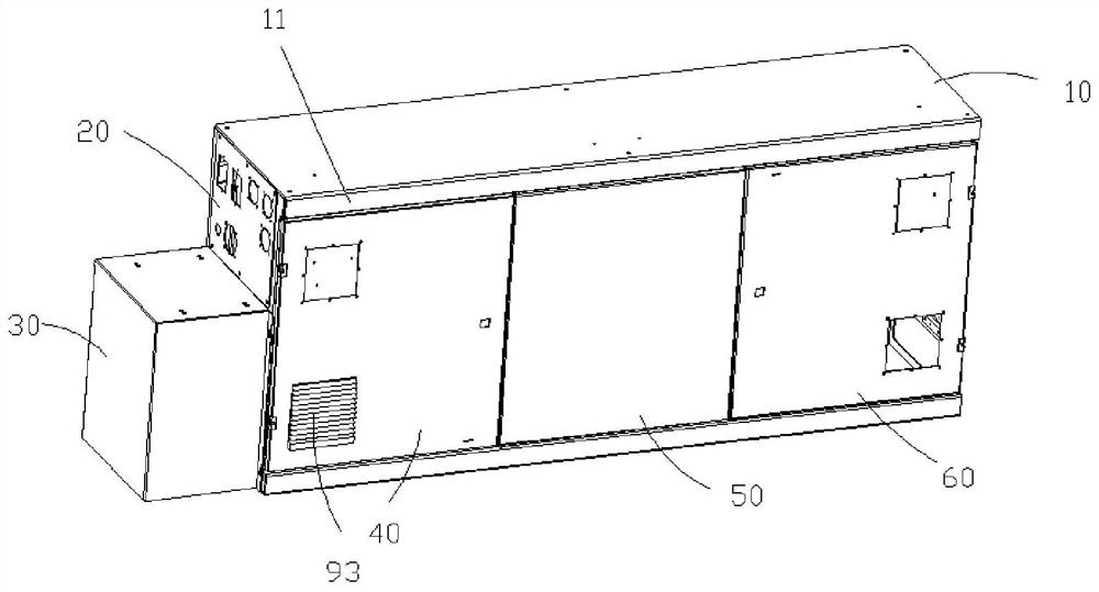
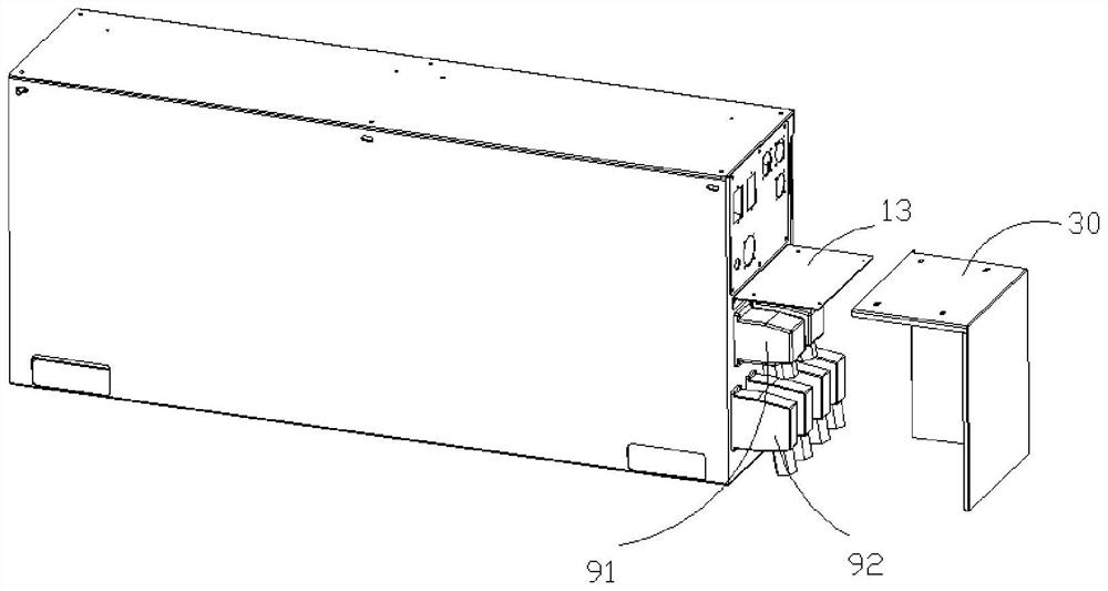
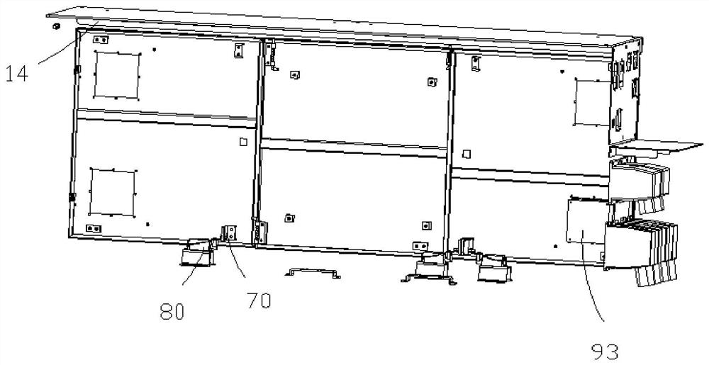
The invention discloses an electric box of an injection molding machine. The electric box comprises an electric box body, a connector protection assembly, a first electric box door, a second electric box door, a third electric box door, a plurality of induction protrusions, a plurality of travel switches which are matched with the induction protrusions in operation and an axial flow fan, a side waterproof protruding table is arranged on the top of the electric box body, a lamp mounting frame is arranged in the interior of the electric box body, a maintenance lamp is arranged on the lamp mounting frame, the tail part of the electric box body is provided with a connector assembly, the connector protection assembly is arranged at the outer side of the connector assembly, the first electric box door is provided with a ventilation opening, and the axial flow fan is arranged at the ventilation opening. The problem of top waterproofing and oil proofing is solved through the side waterproof protruding table, the problem of transportation inconvenience is solved through the split type electric box door, meanwhile, convenience is provided for maintenance personnel through cooperation of the maintenance lamp, the induction protrusions and the travel switches, the problem of maintenance inconvenience is solved, safe and reliable electric box detection components are matched with the maintenance lamp source, and the safety of later maintenance personnel is ensured.

Description

technical field [0001] The invention relates to the field of injection molding, in particular to an injection molding electromechanical box. Background technique [0002] At present, injection molding machines are also known as injection molding machines or injection machines. It is the main molding equipment for making thermoplastics or thermosetting plastics into various shapes of plastic products using plastic molding molds. Divided into vertical, horizontal, all-electric. The injection molding machine heats the plastic, applies high pressure to the molten plastic, and makes it shoot out to fill the mold cavity. The injection system is one of the most important components of the injection molding machine. Generally, there are three main forms: plunger type, screw type, and screw pre-molded plunger injection type. The most widely used is the screw type. Its function is that in a cycle of the injection molding machine, a certain amount of plastic can be heated and plast...

Claims


Application Information

Patent Timeline
Patent Type & Authority Applications(China)
IPC IPC(8): B29C45/17H02B1/28H02B1/46H02B1/48H02B1/56
Inventor 陈松林孙晓波袁中华杜呈表周清华刘媛
Owner BORCH MACHINERY
Learn More