Press fitting device with self-locking pressing function and using method

A pressing device and self-locking technology, applied in the field of pressing tooling, can solve the problems of dimensional deviation, insufficient holding pressure, and high labor intensity, so as to achieve the effect of pressing fit and ensuring stability

Pending Publication Date: 2021-11-02
CHINA THREE GORGES UNIV
View PDF2 Cites 2 Cited by
  • Summary
  • Abstract
  • Description
  • Claims
  • Application Information

AI Technical Summary

Problems solved by technology

The above-mentioned lever-type pressing device has the following problems in the specific use process: (1) The lever-type mechanism needs to apply external force manually, and the manual work intensity is high in the whole process; (2) During the pressing process, it is necessary to use The counterweight maintains the pressure of the lever mechanism. Due to the different required holding pressures, a variety of different types of counterweights are required, which may lead to insufficient holding pressure, resulting in dimensional deviation

Method used


Image

  • Press fitting device with self-locking pressing function and using method
  • Press fitting device with self-locking pressing function and using method

Examples


Embodiment 1

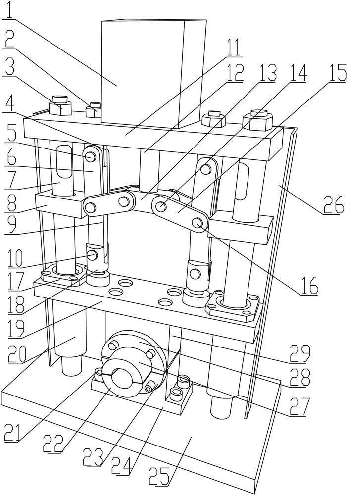
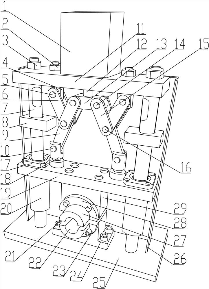
[0035] Such as Figure 1-2 As shown, there is a press-fitting device with self-locking and pressing, which includes a tooling base plate 25, and guide columns 7 arranged in parallel are fixed on both sides of the top of the tooling base plate 25, and a top plate 11 is fixedly installed on the top of the guide column 7; The lower part of the guide column 7 is slidably fitted with a lifting plate 19 through the guide sliding sleeve 20; the middle part of the bottom end of the lifting plate 19 is fixedly equipped with an upper mold assembly; The lower mold assembly is matched with the lower mold assembly, and the thermoplastic pipe fittings to be processed are press-fitted and formed; the lifting plate 19 is connected with the power device for providing press-fit power through a self-locking linkage mechanism; the power device is fixedly installed on the top plate 11 on. This self-locking compression device can be used for the end shrinkage of thermoplastic pipe fittings. It can...

Embodiment 2

[0045] The operation method of the pressing device with self-locking and pressing comprises the following steps:

[0046] Step 1, heating the end portion of the thermoplastic pipe fitting that needs shrinkage cavity through a heating device;

[0047] Step 2, placing the heated thermoplastic pipe fitting end on the lower half mold 22 of the lower mold assembly;

[0048] Step 3: start the power device, drive the piston rod 12 to go down through the cylinder body 1 of the power device, and drive the third connecting rod 15 to go down through the piston rod 12, and drive the first connecting rod 9 and the second connecting rod through the third connecting rod 15 6. At this time, the first connecting rod 9 and the second connecting rod 6 will straighten, and at the same time, the first connecting rod 9 drives the lifting plate 19 to go down along the guide column 7, and the lifting plate 19 drives the upper mold assembly to press down, and then Compress the end of the thermoplasti...


PUM


Abstract

The invention discloses a press fitting device with a self-locking pressing function and a using method. Guide stand columns arranged in parallel are fixed to the two sides of the top of a tool bottom plate, and a top plate is fixedly installed at the tops of the guide stand columns; a lifting plate is arranged on the lower portions of the guide stand columns in a sliding fit mode through guide sliding sleeves; an upper die assembly is fixedly installed in the middle of the bottom end of the lifting plate; the upper die assembly is matched with a lower die assembly fixed to the middle of the top of the tool bottom plate, and press fitting forming is carried out on a thermoplastic pipe fitting to be machined; the lifting plate is connected with a power device used for providing press fitting power through a self-locking connecting rod mechanism; and the power device is fixedly installed on the top plate. The self-locking pressing device can be used for end shrinkage of the thermoplastic pipe fitting, the end of the heated thermoplastic pipe fitting can be pressed in an automatic pressing mode, then the thermoplastic pipe fitting is necked, and after necking is completed, self-locking of a die is achieved through a self-locking mechanism.

Description

technical field [0001] The invention belongs to the field of pressing tooling, and in particular relates to a pressing device with self-locking pressing and an operation method. Background technique [0002] In the shrinkage cavity processing process of some thermoplastic pipe fittings, the basic process is: first heat the end that needs shrinkage cavity, and then send the heated nozzle end to the press-fitting mold for press-fitting, and then Keep the pressure for a period of time until the shrinking end is shaped and reaches the predetermined size specification. [0003] The existing pressing device adopts a manual lever type pressing device. In the process of pressing it, one end of the lever needs to be manually pressed, and the mold is pressed by the lever to shrink the mouth of the nozzle. After the shrinking is completed , use the counterweight to compress the end of the lever and maintain the pressure. The above-mentioned lever-type pressing device has the followin...

Claims


Application Information

Patent Timeline
Patent Type & Authority Applications(China)
IPC IPC(8): B29C57/00
CPCB29C57/00
Inventor 董元发李晓灿刘文戎梁雨晨彭巍
Owner CHINA THREE GORGES UNIV
Why Eureka
Try Eureka