Heat exchanger for fuel oil heater with heat exchange pipe

A fuel-fired heater and heat exchanger technology, applied in fluid heaters, lighting and heating equipment, etc., can solve the problems of limited heat exchange area, excessive heat loss, and inability to obtain high enough thermal efficiency, and reduce production and technology. Retrofit cost, improved thermal efficiency, and effect of shortened warm-up time

Inactive Publication Date: 2007-03-14
SHANDONG UNIV
View PDF0 Cites 4 Cited by
  • Summary
  • Abstract
  • Description
  • Claims
  • Application Information

AI Technical Summary

Problems solved by technology

Because the heat exchange area of ​​this type of heat exchanger is restricted, the heat loss is still relatively large, that is, it cannot obtain a sufficiently high thermal efficiency under the same energy consumption

Method used


Image

  • Heat exchanger for fuel oil heater with heat exchange pipe
  • Heat exchanger for fuel oil heater with heat exchange pipe
  • Heat exchanger for fuel oil heater with heat exchange pipe

Examples


Embodiment 1

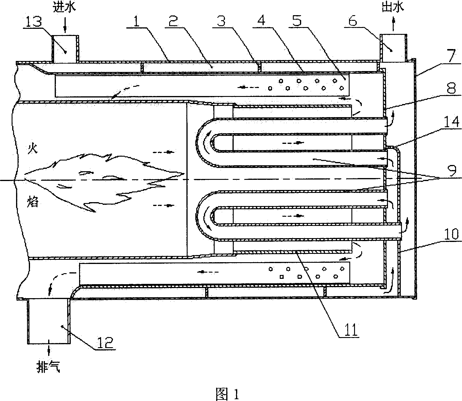
[0021] Figure 1 shows the structure of this embodiment, including heat exchange body 4, heat transfer fin 5, spiral guide fin 3, bottom plate 8, heat exchange body shell 1, water inlet pipe 13, water outlet pipe 6, plug 7, spacer Plate 10 and heat exchange tube 9. The inner wall of the heat exchange body 4 is welded with heat transfer fins 5 distributed along the circumferential direction, and each heat transfer fin is welded along the axial direction. The outer wall of the heat exchanging body 4 is welded with a spiral guide fin 3 , and the cross section of the spiral guide fin 3 can be rectangular, triangular, trapezoidal or circular. The bottom of the heat exchange body 4 is welded with a bottom plate 8 to seal the heat exchange body 4 and isolate the high-temperature gas in the combustion chamber from the circulating water. The heat exchange tube 9 is installed on the bottom plate 8 and is on the high temperature gas side. The shell 1 is set on the outside of the heat ex...

Embodiment 2

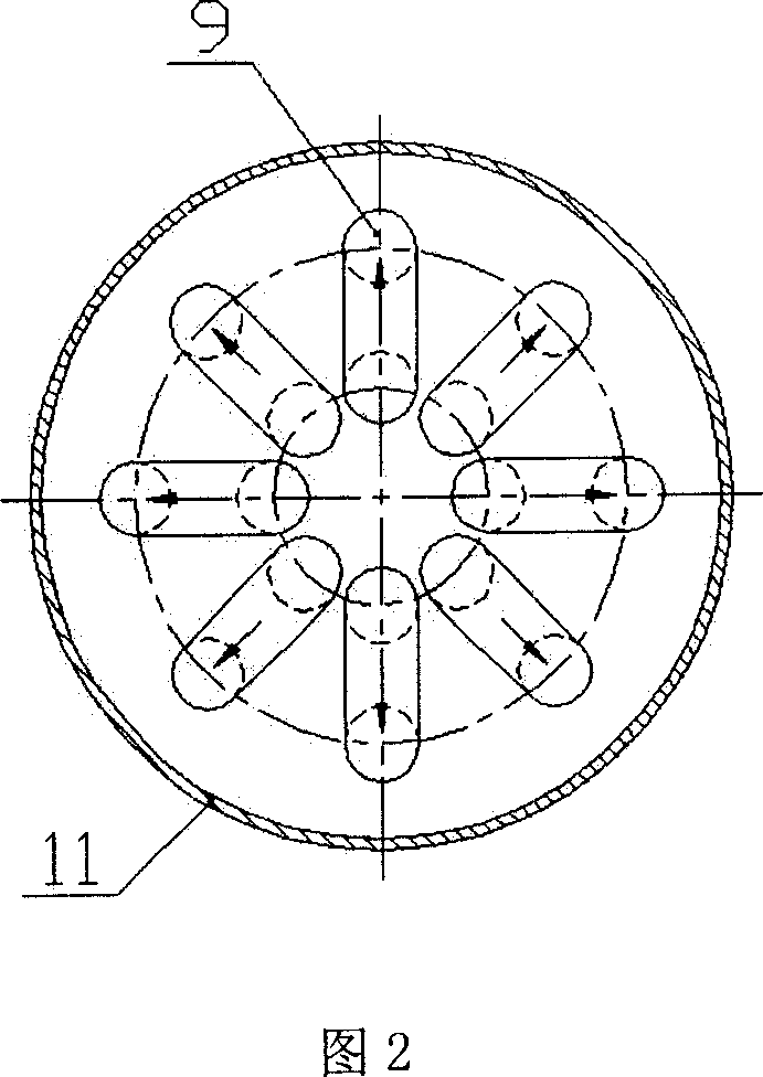
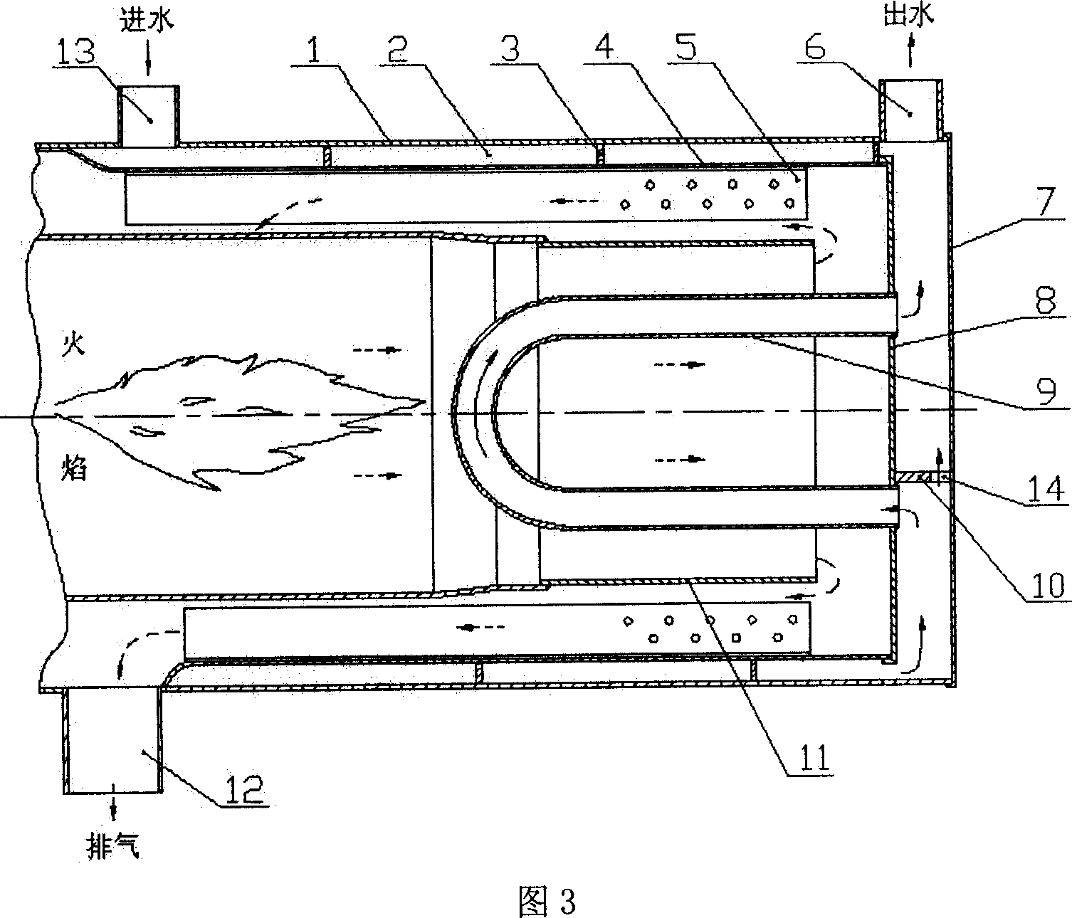
[0024] Figure 3 shows the structure of this embodiment. The difference between this embodiment and Embodiment 1 is that the heat exchange tubes 9 in this embodiment are connected in series at the end of the spiral water chamber in parallel at a certain interval in the flame cylinder. , each heat exchange tube is perpendicular to the bottom plate 8, as shown in FIG. 4 . The partition 10 is close to the upper edge of the water inlet of the heat exchange tube, and is connected with the bottom plate 8 and the plug 7. A water outlet chamber is formed above the partition, and a water inlet chamber is formed below. The partition plate 10 can be arranged horizontally as a straight plate, or can be arranged with a slightly higher slope at the end of the bypass hole 14, so as to facilitate exhaust.

Embodiment 3

[0026] FIG. 5 shows the structure of this embodiment. The difference between this embodiment and Embodiment 1 and Embodiment 2 is that this embodiment uses a spiral heat exchange tube 9 , as shown in FIGS. 5 and 6 . The center of the spiral tube coincides with the axis of the burner flame tube 11, the water inlet end is located at the center of the bottom plate 8, and the partition plate 10 is close to the upper edge of the water inlet of the heat exchange tube and connected with the bottom plate 8 and the plug 7 to form the water inlet and outlet. cavity.

[0027] In a specific application, if the flame flow section of the burner flame tube is constant, when there are too many heat exchange tubes or the tube diameter is too thick, the high-temperature gas flow resistance will increase and the back pressure will increase, thus affecting the normal combustion of the burner . At this time, the number of heat exchange tubes can be appropriately reduced or the diameter of the hea...


PUM


Abstract

The invention provides a heat exchanging equipment for fuel oil heater with heat exchanging pipe, comprising heat exchanging body, heat-conducting plate, shell, heat exchanging pipe, insulation board and helical guiding plate. Heat-conducting plate is distributed on the inside wall of heat exchanging body and helical guiding plate is set on the outside wall of heat exchanging body; the bottom of heat exchanging body is sealed by board and heat exchanging pipe is set on the board; shell is mounted on the heat exchanging body and helical guiding plate is set between them; the frontal end of shell is connected with heat exchanging body together and there is a plug at the back end; helical water cavity is formed by helical guiding plate between heat exchanging body and shell, heat exchanging pipe is connected to the end of helical water cavity in series; insulation board is set between plug and board; inlet and outlet pipes are set at two ends of shell respectively. The heat exchanging pipe can improve heat exchanging area and strengthen heat exchanging so that heat efficiency of heater is improved in the invention. Heat efficiency of fuel oil heater can improve more than 8% and bigger transporting declared power is gained in the invention.

Description

technical field [0001] The invention relates to a heat exchanger for a liquid fuel heater, belonging to the technical field of fuel heaters. Background technique [0002] As an independent heating device, the fuel heater has been widely used for heating in low-temperature environments and engine preheating for various transport machinery such as automobiles and ships. As a key component of a fuel heater, the heat exchanger has a significant impact on the heat exchange efficiency and other properties of the heater. At present, most liquid fuel heaters use spiral water chambers for heat exchange. Because the heat exchange area of ​​this type of heat exchanger is restricted, the heat loss is still relatively large, that is, it cannot obtain a sufficiently high thermal efficiency under the same energy consumption. In particular, when the fuel heater is installed as an auxiliary system on a vehicle or device with limited length, width and height, it is particularly important to...

Claims


Application Information

Patent Timeline
Patent Type & Authority Applications(China)
IPC IPC(8): F24H9/00
Inventor 毛华永李国祥王伟白书战潘世艳
Owner SHANDONG UNIV
Why Eureka
Try Eureka