Knuckle bearing structure

A kind of joint bearing and inner ring technology, applied in the direction of bearing components, shafts and bearings, sliding contact bearings, etc., can solve the problems of small radial force, thin outer ring wall thickness, inability to separate, etc., to increase the axial load The effect of increasing the radial bearing capacity and reducing the production cost

Inactive Publication Date: 2015-07-08
新昌县明瑞关节轴承有限公司
View PDF0 Cites 4 Cited by
  • Summary
  • Abstract
  • Description
  • Claims
  • Application Information

AI Technical Summary

Problems solved by technology

[0002] The joint bearing is a spherical sliding bearing. The basic type is composed of an inner and outer ring with a spherical sliding spherical contact surface. The inner ring and the outer ring are processed and formed at one time. The rod end joint bearing is provided with a pulling rod on the outer ring of the joint bearing. existing see figure 1 , the structure of the rod end joint bearing is composed of an outer ring 1 with an inner spherical surface and a pull rod and an inner ring 2 with an outer spherical surface. Since the rod end joint bearing structure has a pull rod, the inner ring and the outer ring cannot be Processing and forming, the existing structure of the rod end spherical plain bearing is usually to use the basic type of spherical plain bearing embedded in a jacket 3 with a tie rod, or to set the flanging on the outer ring, put the inner ring into the outer ring and then close the flanging, To put the inner ring into the outer ring, because the rod end spherical plain bearing needs to bear a large load, the basic type of spherical plain bearing is embedded in a casing with a tie rod. While ensuring the overall size of the rod end spherical plain bearing, it is bound to It is necessary to reduce the wall thickness of the outer ring, which reduces the radial bearing capacity of the rod end joint bearing; set the flange on the outer ring, put the inner ring into the outer ring and then close the flange to realize the inner ring into the outer ring. In the outer ring, the radial force is small, and the inner ring and the outer ring cannot be separated after forming, and the inner ring or the outer ring cannot be replaced after being damaged, so they have to be scrapped as a whole, which increases the production cost

Method used


Image

  • Knuckle bearing structure
  • Knuckle bearing structure
  • Knuckle bearing structure

Examples


Embodiment Construction

[0011] Below in conjunction with accompanying drawing, the present invention will be further described:

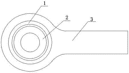
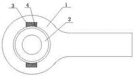
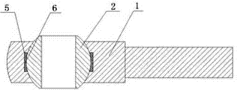
[0012] See figure 2 , a rod end joint bearing structure, which includes an outer ring 1 with a tie rod, an inner ring 2 is arranged inside the outer ring 1, a notch 3 is arranged on the inner side of both ends of the outer ring 1, and the length of the notch 3 is equal to the outer diameter of the inner ring 2 Correspondingly, the width of the gap 3 corresponds to the thickness of the inner ring 2, the inner ring 2 is put into the outer ring 1 through the gap 3, the inner side of the outer ring 1 is spherical, the outer side of the inner ring 2 is spherical, and the outer ring 1 and the inner ring 2 Form a consistent spherical contact; there is a notch 3 on the inner side of both ends of the outer ring 1, and the inner ring 2 is inserted into the notch 3 transversely and then rotated to realize the cooperation between the inner spherical surface of the outer ring 1 and th...


PUM


Abstract

The invention relates to a knuckle bearing structure. The knuckle bearing structure comprises an outer ring with a pulling rod, wherein the outer ring is internally provided with an inner ring. The knuckle bearing structure is characterized in that the inner sides of the two ends of the outer ring are respectively provided with a gap; the length of the gap corresponds to the outer diameter of the inner ring; the width of the gap corresponds to the thickness of the inner ring; the inner ring is placed in the outer ring by the gaps; and the outer ring and the inner ring form matched spherical-surface contact. The knuckle bearing structure has the advantages that the inner sides of the two ends of the outer ring are respectively provided with the gap, the length of the gap corresponds to the outer diameter of the inner ring, the width of the gap corresponds to the thickness of the inner ring, the inner ring is horizontally placed in the gaps and is placed into the outer ring by rotation, and the outer ring and the inner ring form matched spherical-surface contact, and since the inner ring is placed into the outer ring by rotation, the separation of the inner ring and the outer ring is conveniently realized, the convenient replacement of the inner ring or the outer ring is realized and the production cost is effectively reduced.

Description

technical field [0001] The invention relates to a joint bearing structure. Background technique [0002] The joint bearing is a spherical sliding bearing. The basic type is composed of an inner and outer ring with a spherical sliding spherical contact surface. The inner ring and the outer ring are processed and formed at one time. The rod end joint bearing is provided with a pulling rod on the outer ring of the joint bearing. existing see figure 1 , the structure of the rod end joint bearing is composed of an outer ring 1 with an inner spherical surface and a pull rod and an inner ring 2 with an outer spherical surface. Since the rod end joint bearing structure has a pull rod, the inner ring and the outer ring cannot be Processing and forming, the existing structure of the rod end spherical plain bearing is usually to use the basic type of spherical plain bearing embedded in a jacket 3 with a tie rod, or to set the flanging on the outer ring, put the inner ring into the out...

Claims


Application Information

Patent Timeline
Patent Type & Authority Applications(China)
IPC IPC(8): F16C23/04F16C33/04F16N15/02
Inventor 许明超
Owner 新昌县明瑞关节轴承有限公司
Why Eureka
Try Eureka