Lifting column and method for controlling height thereof

A lifting column and height technology, which is applied in the field of lifting columns and mobile X-ray devices, can solve the problems of difficulty in obtaining accuracy, difficulty in height adjustment, and bulky devices, and achieve the effects of increased safety, easy transportation, and increased service life

Pending Publication Date: 2021-11-02
SOLUTIONS FOR TOMORROW
View PDF0 Cites 0 Cited by
  • Summary
  • Abstract
  • Description
  • Claims
  • Application Information

AI Technical Summary

Problems solved by technology

However, while range may have been improved, imaging still cannot be performed close to the floor
Furthermore, although the disclosed device can be placed into a compact shape, it is still bulky
One of the reasons the unit is bulky is the use of a counterweight
In addition, the lifting column has many parts and is thus complex in its construction
So its control can also be complex
Additionally, it may be difficult to achieve sufficient accuracy with a device that has a counterweight drive mechanism
Also, it can be difficult to adjust the height quickly enough

Method used


Image

  • Lifting column and method for controlling height thereof
  • Lifting column and method for controlling height thereof
  • Lifting column and method for controlling height thereof

Examples


Embodiment Construction

[0054] Specific embodiments of the present invention will now be described with reference to the accompanying drawings. However, this invention may be embodied in many different forms and should not be construed as limited to these embodiments set forth herein; rather, these embodiments are provided so that this disclosure will be thorough and complete, and will fully convey to those skilled in the art. convey the scope of the invention. The terms shown in the drawings and used to describe these embodiments in detail are not intended to limit the present invention. In the drawings, like numbers refer to like elements.

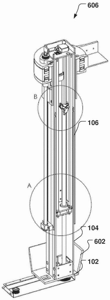
[0055] The following description focuses on an embodiment of the invention applicable to a mobile X-ray device and in particular to a lifting column of a mobile X-ray device. However, it will be appreciated that the invention is not limited to this application, but may be applied to many other X-ray installations, including for example stationary X-ray instal...


PUM


Abstract

The invention discloses a lifting column for an X-ray device. The X-ray device is movable, where the column is preferably rotationally fixed relative to a base of the X-ray device, and the column is provided with a plurality of sections and a first height adjustment unit; the plurality of sections include a first section and a second section, the first section has a first end part and an opposite second end part, and the first end part is arranged on the base; the second section has a first end part and an opposite second end part, and the second section is arranged at the first end part with an overlap of the second end part of the first section and is movable relative to the first section; and the first height adjustment unit comprises at least one first threaded slender member fixed at one of the first section and the second section, and a first threaded receiving element arranged at the other one of the first section and the second section and engaged with the threaded slender member in a pairing manner to adjust the height of the column.

Description

[0001] This application is a divisional application of the application number 201480026975.X with the date of entering the Chinese national phase on November 11, 2015. technical field [0002] The present invention generally relates to the field of X-ray devices. More particularly, the present invention relates to mobile X-ray devices and even more particularly to a lifting column of a mobile X-ray device. Background technique [0003] A lifting column has been disclosed in US2011 / 0249807A1 which allows lower imaging than usual. However, while the range may have been improved, imaging still cannot be performed close to the floor. Furthermore, although the disclosed device can be packed into a compact shape, it is still bulky. One of the reasons for the bulkiness of the device is the use of a counterweight. In addition, the lifting column has many parts and is thus complex in its construction. Its control can therefore also be complex. Additionally, it may be difficult t...

Claims


Application Information

Patent Timeline
Patent Type & Authority Applications(China)
IPC IPC(8): B66F3/08B66F3/44A61B6/00
Inventor M·古德斯特兰德M·G·K·伊恩维斯森J·伯特
Owner SOLUTIONS FOR TOMORROW
Why Eureka
Try Eureka