
Communication module micro-connection structure of optical fiber splitter and use method

A fiber optic splitter, communication module technology, applied in the fiber mechanical structure, optical waveguide coupling, optical guide and other directions, can solve the problem that the split cable cannot be assembled or separated as a whole or installed in sequence.

Pending Publication Date: 2021-11-02
山西常泽科技有限公司
View PDF11 Cites 0 Cited by
  • Summary
  • Abstract
  • Description
  • Claims
  • Application Information

AI Technical Summary

Problems solved by technology

[0004] The purpose of the present invention is to provide a communication module micro-connection structure and usage method of an optical fiber splitter, so as to solve the problem that the sub-cables proposed in the above-mentioned background technology cannot be assembled or separated for overall installation or sequential installation

Method used


Image

  • Communication module micro-connection structure of optical fiber splitter and use method
  • Communication module micro-connection structure of optical fiber splitter and use method
  • Communication module micro-connection structure of optical fiber splitter and use method

Examples


Embodiment Construction

[0030]The following will clearly and completely describe the technical solutions in the embodiments of the present invention with reference to the accompanying drawings in the embodiments of the present invention. Obviously, the described embodiments are only some, not all, embodiments of the present invention. Based on the embodiments of the present invention, all other embodiments obtained by persons of ordinary skill in the art without making creative efforts belong to the protection scope of the present invention.

[0031] see Figure 1-6 , the present invention provides a technical solution:

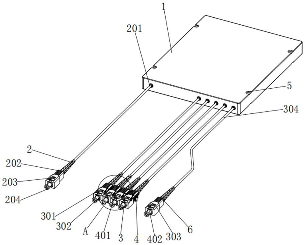
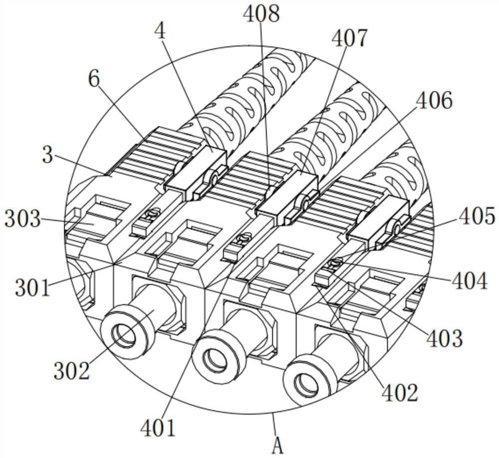
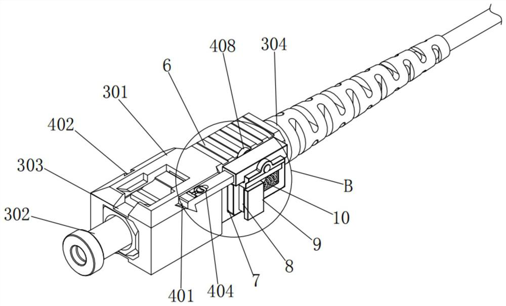
[0032] A communication module micro-connection structure of an optical fiber splitter, comprising an optical fiber splitter 1 and a mounting hole 5, the left and right ends of the optical fiber splitter 1 are processed with mounting holes 5 inside the front and rear sides, and the optical fiber splitter 1 The two sides of the front end are respectively equipped with a main line ass...


PUM


Abstract

A communication module micro-connection structure of an optical fiber splitter disclosed by the present invention comprises an optical fiber splitter and installation holes, the installation holes are processed in the interiors of the front and rear sides of the left and right ends of the optical fiber splitter, and a main line assembly and a branching assembly are installed on the two sides of the front end of the optical fiber splitter respectively; second springs are arranged on the upper side and the lower side of the right portion of a second sliding block correspondingly, and the two sides of the second springs are fixedly connected with the second sliding block and a right side plate correspondingly. According to the communication module micro-connection structure of the optical fiber splitter and the use method thereof, through cooperation among the branch cable shells, a left side plate, a first sliding blocks and the branch cable connectors, after the branch cable shells are assembled, the first sliding blocks can abut against the inner wall of the adjacent left side plate to achieve synchronous movement of the multiple branch cable shells, and when respective installation is needed, respective installation with the optical fiber jacks can be realized without assembling, so that the problem that the existing branch cable cannot be assembled or separated for integral installation or sequential installation is solved.

Description

technical field [0001] The invention relates to the technical field, in particular to a micro-connection structure of a communication module of an optical fiber splitter and a use method thereof. Background technique [0002] Optical fiber is the abbreviation of optical fiber, which is a kind of fiber made of glass or plastic, which can be used as a light transmission tool. Optical fiber splitter is a device used to realize the splitting and combining of light wave energy. The transmitted optical energy is allocated to two or more optical fibers according to a predetermined ratio, or the optical energy transmitted in multiple optical fibers is combined into one optical fiber. Optical fiber splitters are widely used in optical fiber communication systems, radio and television networks and other fields . [0003] Although the existing technology can realize the micro-connection of the communication module of the optical fiber splitter, there is a problem that the sub-cables c...

Claims


Application Information

Patent Timeline
Patent Type & Authority Applications(China)
IPC IPC(8): G02B6/44G02B6/40
CPCG02B6/4441G02B6/406
Inventor 刘志超杨晓伟
Owner 山西常泽科技有限公司
Learn More