Arc extinguish chamber and tank-type circuit breaker

A static arc contact and moving contact technology, applied in circuit breaker parts, circuit breaker contacts, etc., to achieve the effect of being conducive to miniaturization, miniaturization, and reducing radial dimensions

Pending Publication Date: 2021-11-02
STATE GRID ZHEJIANG ELECTRIC POWER +1
View PDF1 Cites 1 Cited by
  • Summary
  • Abstract
  • Description
  • Claims
  • Application Information

AI Technical Summary

Problems solved by technology

[0006] The object of the present invention is to provide an arc extinguishing chamber to solve the problem that in the prior art, the rotation axis of the rotating connecting rod is on the center line of the second contact. In order to avoid the long section of the rotating connecting rod, it is necessary to make the arc extinguishing chamber larger technical problem; the purpose of the present invention is also to provide a tank circuit breaker

Method used


Image

  • Arc extinguish chamber and tank-type circuit breaker
  • Arc extinguish chamber and tank-type circuit breaker
  • Arc extinguish chamber and tank-type circuit breaker

Examples


Embodiment 1

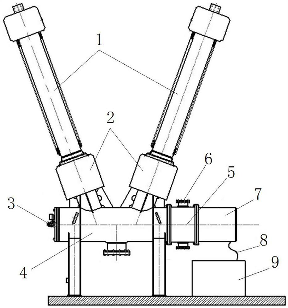
[0046]Such as figure 1 As shown, the tank type circuit breaker includes an arc extinguishing chamber 4, a transition cylinder 5 and a repulsion mechanism 7 arranged in sequence from left to right. The lower end of the bushing 1 is equipped with a current transformer 2, the current enters and exits the arc extinguishing chamber 4 through the inlet and outlet bushing 1, and the current transformer 2 is used to monitor the line current; the left flange of the arc extinguishing chamber 4 is provided with a density meter 3 , the density meter 3 is used to detect the insulating gas density in the arc extinguishing chamber 4; the repulsion mechanism 7 is connected to the power box 9 through a cable 8. Wherein, the repulsion mechanism 7 constitutes a driving mechanism; the power supply box 9 is designed in a separate form, and the arrangement is flexible.

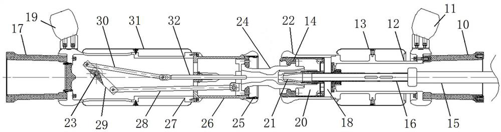
[0047] Such as figure 2 As shown, the arc extinguishing chamber 4 includes a casing, and a moving contact assembly and a stati...

Embodiment 2

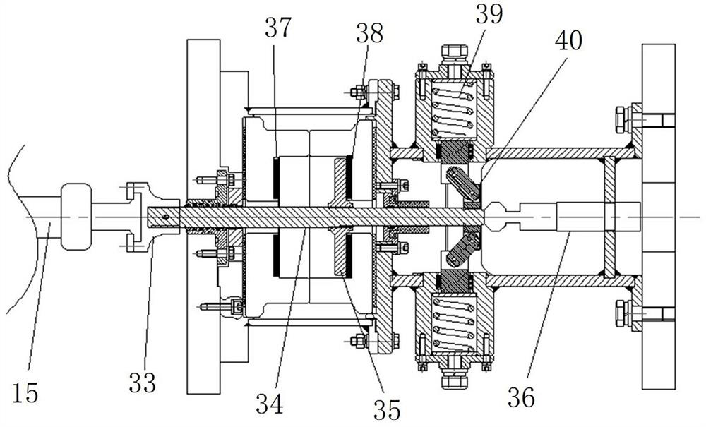
[0061] The difference between this embodiment and Embodiment 1 is that in Embodiment 1, when the rotating plate 29 is perpendicular to the static arc contact 32 , the center point of the rotating plate is on the reference plane. In this embodiment, when the rotating arm is perpendicular to the static arc contact, the center point of the rotating arm and the rotating axis of the rotating shaft are at same side of the reference plane. In other embodiments, when the rotating arm is perpendicular to the static arc contact, under the condition that the rotating axis of the rotating shaft and the hinge axis of the fourth hinged shaft are on the same side of the reference plane, the center point of the rotating arm is in the on both sides of the reference plane.

Embodiment 3

[0063] The difference between this embodiment and Embodiment 1 is that in Embodiment 1, the rotating arm is a rotating plate 29 . In this embodiment, the rotating arm is a rotating rod.


PUM


Abstract

The invention relates to an arc extinguish chamber and a tank-type circuit breaker. The arc extinguish chamber comprises: a moving contact assembly, which comprises a moving contact base and a nozzle, wherein the nozzle can reciprocate in the moving contact base; a static contact assembly which comprises a static contact base, a static support and a static arc contact, wherein the static arc contact is assembled in the static contact base in a guiding and sliding manner, and a rotating shaft is arranged on the inner side wall of the static support; a connecting rod mechanism which comprises a movable end connecting rod, a static end connecting rod and a rotating arm, wherein the rotating arm is rotationally assembled on the rotating shaft, the rotating arm is provided with a long section and a short section, one end of the movable end connecting rod is hinged to the nozzle, the other end of the movable end connecting rod is hinged to the long section, one end of the static end connecting rod is hinged to the static arc contact, and the other end of the static end connecting rod is hinged to the short section; and a plane which passes through the center line of the static contact base and is parallel to the hinge axis of the movable end connecting rod and the long section is defined as a reference plane, and the rotating axis of the rotating arm and the hinge axis of the static end connecting rod and the short section are located on the same side of the reference plane.

Description

technical field [0001] The invention relates to an arc extinguishing chamber and a pot circuit breaker. Background technique [0002] With the continuous increase of the national economy and the scale of the power grid, the transient stability of the AC grid system, the short-circuit current exceeding the standard, and the transient overvoltage of the busbar of the DC transmission system have become the key to restricting the scale of the grid and the stability of the system operation. Therefore, reducing the breaking time of the tank circuit breaker can effectively solve the above problems. [0003] The Chinese invention patent application whose publication number is CN109767949A discloses a kind of arc extinguishing chamber, such as figure 1 with figure 2 As shown, it includes a first contact assembly, a second contact assembly and a linkage mechanism, the first contact assembly includes a first contact, a spout fixedly connected to the first contact, and a spout pressu...

Claims


Application Information

Patent Timeline
Patent Type & Authority Applications(China)
IPC IPC(8): H01H73/18H01H73/04
CPCH01H73/18H01H73/04
Inventor 王文博钟建英金玉琪徐华段晓辉魏建巍孙珂珂杨珂熊萍萍张利欣朱秋楠王鹏超韩峰孙英杰刘煜李新刚李海文
Owner STATE GRID ZHEJIANG ELECTRIC POWER
Why Eureka
Try Eureka