A robot spraying production device

A technology of production device and spraying device, applied in the direction of spraying device, etc., can solve the problems of poor spraying uniformity, low processing efficiency, jitter, etc., and achieve the effect of improving spraying thickness and good adaptability

Active Publication Date: 2021-12-10
海安苏博机器人科技有限公司
View PDF6 Cites 0 Cited by
  • Summary
  • Abstract
  • Description
  • Claims
  • Application Information

AI Technical Summary

Problems solved by technology

[0004] Aiming at the deficiencies of the prior art, the present invention provides a robot spraying production device, which solves the problem that the pipe fittings need to be rotated when the pipe fittings are sprayed in the current robot processing process, and the device that drives the pipe fittings to rotate needs to be clamped on the pipe fittings. As a result, the clamping part of the pipe cannot be sprayed. After the spraying is completed, the clamping part needs to be resprayed. The processing efficiency is low, and the pipe will vibrate under the action of centrifugal force when the pipe is rotated, resulting in poor spraying uniformity.

Method used


Image

  • A robot spraying production device
  • A robot spraying production device
  • A robot spraying production device

Examples


Embodiment 1

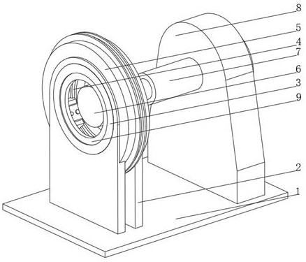
[0037] see Figure 1-3 , the present invention provides a technical solution: a robot spraying production device, specifically comprising:

[0038] A fixed plate 1, the top of the fixed plate 1 is fixedly connected with a fixed frame 2, the top of the fixed frame 2 is fixedly connected with a fixed ring 3, and the inside of the fixed ring 3 is provided with a slideway 4;

[0039] Rotary spraying device 5, the rotary spraying device 5 is arranged inside the fixed ring 3 and is slidingly connected with the inner wall of the slideway 4;

[0040] A fixing device 6, the fixing device 6 is arranged inside the fixing ring 3, one side of the fixing device 6 is fixedly connected with a telescopic rod 7, and one end of the telescopic rod 7 is fixedly connected with a fixed bracket 8;

[0041] A support ring 9, the support ring 9 is fixed on one side of the fixed ring 3, and the inner diameter of the support ring 9 is smaller than the inner diameter of the fixed ring 3;

[0042] Describe...

Embodiment 2

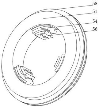
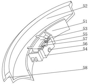
[0048] see Figure 1-5 On the basis of Embodiment 1, the present invention provides a technical solution: the fixing device 6 includes a fixed plate 61, and the side of the fixed plate 61 is provided with a telescopic hole 62, and the inner wall of the telescopic hole 62 is slidably connected with a push rod 63 , the inner wall of the fixed disk 61 is provided with a rotating disk 66, the side of the rotating disk 66 is fixedly connected with an arc-shaped protrusion 64, and one side of the rotating disk 66 is fixedly connected with a driving lever 65, and the driving lever 65 is far away from the rotating disk One end of 66 passes through the fixed plate 61 and extends to the outside of the fixed plate 61. The side of the fixed plate 61 close to the shift lever 65 is fixedly connected with the telescopic rod 7. The telescopic holes 62 are provided in multiple groups and evenly distributed on the fixed plate 61. All around, the side of the rotating disk 66 is fixedly connected...


PUM


Abstract

The invention discloses a robot spraying production device, which specifically includes: a fixed plate, the top of the fixed plate is fixedly connected with a fixed frame, the top of the fixed frame is fixedly connected with a fixed ring, and a slideway is provided inside the fixed ring; device, the rotating spraying device is arranged inside the fixed ring and is slidingly connected with the inner wall of the slideway; the fixing device, the fixing device is arranged inside the fixed ring, one side of the fixing device is fixedly connected with a telescopic rod, and one end of the telescopic rod is fixedly connected There is a fixed bracket; a support ring, the support ring is fixed on one side of the fixed ring, and the inner diameter of the support ring is smaller than the inner diameter of the fixed ring. It relates to the field of spraying technology. The robot spraying production device can avoid uneven spraying caused by shaking caused by centrifugal force, and can adjust the spraying thickness according to the materials of different pipe fittings, and has good adaptability.

Description

technical field [0001] The invention relates to the technical field of spraying, in particular to a robot spraying production device. Background technique [0002] Spraying is a coating method in which spray guns or disc atomizers are dispersed into uniform and fine droplets by means of pressure or centrifugal force and applied to the surface of the object to be coated. It can be divided into air spraying, airless spraying, electrostatic spraying and various derivative methods of the above basic spraying forms, such as large flow and low pressure atomization spraying, thermal spraying, automatic spraying, multi-group spraying, etc. The production efficiency of spraying operations is high, It is suitable for manual operation and industrial automation production. It has a wide range of applications, mainly in hardware, plastics, furniture, military industry, ships and other fields. It is the most commonly used coating method today; the environmental requirements for spraying o...

Claims


Application Information

Patent Timeline
Patent Type & Authority Patents(China)
IPC IPC(8): B05B13/04B05B12/08B05B13/02
CPCB05B13/0421B05B12/084B05B13/0285B05B13/0278
Inventor 龚勋李文章
Owner 海安苏博机器人科技有限公司
Why Eureka
Try Eureka