Coating spraying device and method for road maintenance

A technology of road maintenance and spraying equipment, which is applied in the direction of spraying equipment, roads, roads, etc., which can solve the problems affecting the quality of marking lines, changes in marking line width and thickness, etc., and achieve the effect of increasing performance and avoiding uneven spraying

Active Publication Date: 2021-02-23
NANJING MAOLE ENG MATERIALS CO LTD
View PDF5 Cites 2 Cited by
  • Summary
  • Abstract
  • Description
  • Claims
  • Application Information

AI Technical Summary

Problems solved by technology

[0002] In the process of highway maintenance, it is necessary to re-mark the damaged or blurred marking area. When using the paint spraying device to mark the line, first remove the old marking, and then push the car body through the spraying head of the device. Spray the paint to the construction area and mark the construction area. In order to ensure the quality of the line, it is necessary to adjust the distance between the spray head and the road surface before construction so that the width and thickness of the marking line meet the standard. However, adjust The final spraying head will not change during the process of device moving and marking, because the road surface is not level, and the pulleys of the vehicle body and the spraying head are not on the same horizontal line, when the vehicle body pulley and the spraying head correspond When the height of the road surface is different, the distance between the spraying head and the construction area will change, resulting in changes in the width and thickness of the sprayed markings, which will affect the quality of the markings. Therefore, we propose a paint spraying device for road maintenance and spraying method

Method used


Image

  • Coating spraying device and method for road maintenance
  • Coating spraying device and method for road maintenance
  • Coating spraying device and method for road maintenance

Examples


Embodiment Construction

[0021] The following will clearly and completely describe the technical solutions in the embodiments of the present invention with reference to the accompanying drawings in the embodiments of the present invention. Obviously, the described embodiments are only some, not all, embodiments of the present invention. Based on the embodiments of the present invention, all other embodiments obtained by persons of ordinary skill in the art without making creative efforts belong to the protection scope of the present invention.

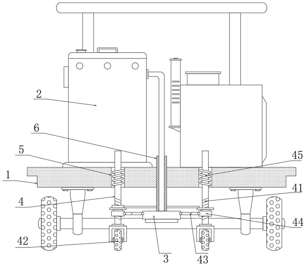
[0022] The invention provides a technical solution: a paint spraying device for road maintenance, please refer to figure 1 , including car body 1 and barrel 2;

[0023] see figure 1 , the bucket 2 is fixedly installed on the top outer wall of the car body 1, the outer wall of the bottom of the car body 1 is provided with two sets of openings 5, and the outer wall of the bottom of the car body 1 is provided with two sets of guiding devices 4, the guiding devic...


PUM


Abstract

The invention discloses a coating spraying device for road maintenance, and belongs to the technical field of road maintenance equipment. The device comprises a vehicle body and a material barrel, thematerial barrel is fixedly mounted on the outer wall of the top of the vehicle body, two groups of openings are formed in the outer wall of the bottom of the vehicle body, and two groups of guide devices are arranged on the outer wall of the bottom of the vehicle body; the guide device comprises guide rods slidably inserted into the inner cavities of the openings, guide wheels are fixedly mountedat the bottom ends of the guide rods, a spraying head is arranged between the two guide rods, and the end, away from the spraying head, of the hose extends to the outer wall of the top of the vehiclebody and communicates with the outer wall of the right side of the material barrel. The guide whees and the spraying head in the device are located on the same horizontal line, the guide wheels drivethe guide rods to move up and down in the inner cavity of the openings, the spraying head can change along with the height change of the road surface, and therefore the distance between the sprayinghead and the marking area is kept unchanged, and uneven marking spraying caused by factors of the road surface is avoided.

Description

technical field [0001] The invention relates to the technical field of road maintenance equipment, in particular to a paint spraying device and a spraying method for road maintenance. Background technique [0002] In the process of highway maintenance, it is necessary to re-mark the damaged or blurred marking area. When using the paint spraying device to mark the line, first remove the old marking, and then push the car body through the spraying head of the device. Spray the paint to the construction area and mark the construction area. In order to ensure the quality of the line, it is necessary to adjust the distance between the spray head and the road surface before construction so that the width and thickness of the marking line meet the standard. However, adjust The final spraying head will not change during the process of device moving and marking, because the road surface is not level, and the pulleys of the vehicle body and the spraying head are not on the same horizo...

Claims


Application Information

Patent Timeline
Patent Type & Authority Applications(China)
IPC IPC(8): E01C23/22B05B15/68
CPCE01C23/22B05B15/68Y02P70/10
Inventor 宫建民
Owner NANJING MAOLE ENG MATERIALS CO LTD
Why Eureka
Try Eureka