Discharging device for steel bar automatic forming equipment

An automatic forming and equipment technology, which is applied in the field of steel bar cutting, can solve problems such as unfavorable steel bar use, steel bar damage, and steel bar scattered, and achieve the effects of avoiding steel bar damage, improving straightening effect, and being easy to use

Inactive Publication Date: 2021-11-05
陈永康
View PDF0 Cites 0 Cited by
  • Summary
  • Abstract
  • Description
  • Claims
  • Application Information

AI Technical Summary

Problems solved by technology

[0002] In the production of steel bars, in order to facilitate the use of subsequent steel bars, the length of the steel bars is usually produced longer. When in use, the steel bars are cut and shaped according to the needs. Therefore, when the steel bars are transported, the steel bars are usually rolled up and then processed. In this way, during use, it is necessary to use a straightening machine to straighten the steel bars, and when the steel bars are transported to the straightening machine through the unloading device, since most of the steel bars are scattered, when the unloading device transports the steel bars, the steel bars are easy to be Bending and twisting will cause damage to the steel bar, which is not conducive to the use of the steel bar

Method used


Image

  • Discharging device for steel bar automatic forming equipment
  • Discharging device for steel bar automatic forming equipment
  • Discharging device for steel bar automatic forming equipment

Examples


Embodiment Construction

[0031]The technical solutions in the embodiments of the present invention will be clearly and completely described below in conjunction with the embodiments of the present invention. Apparently, the described embodiments are only some of the embodiments of the present invention, not all of them. Based on the embodiments of the present invention, all other embodiments obtained by persons of ordinary skill in the art without creative efforts fall within the protection scope of the present invention.

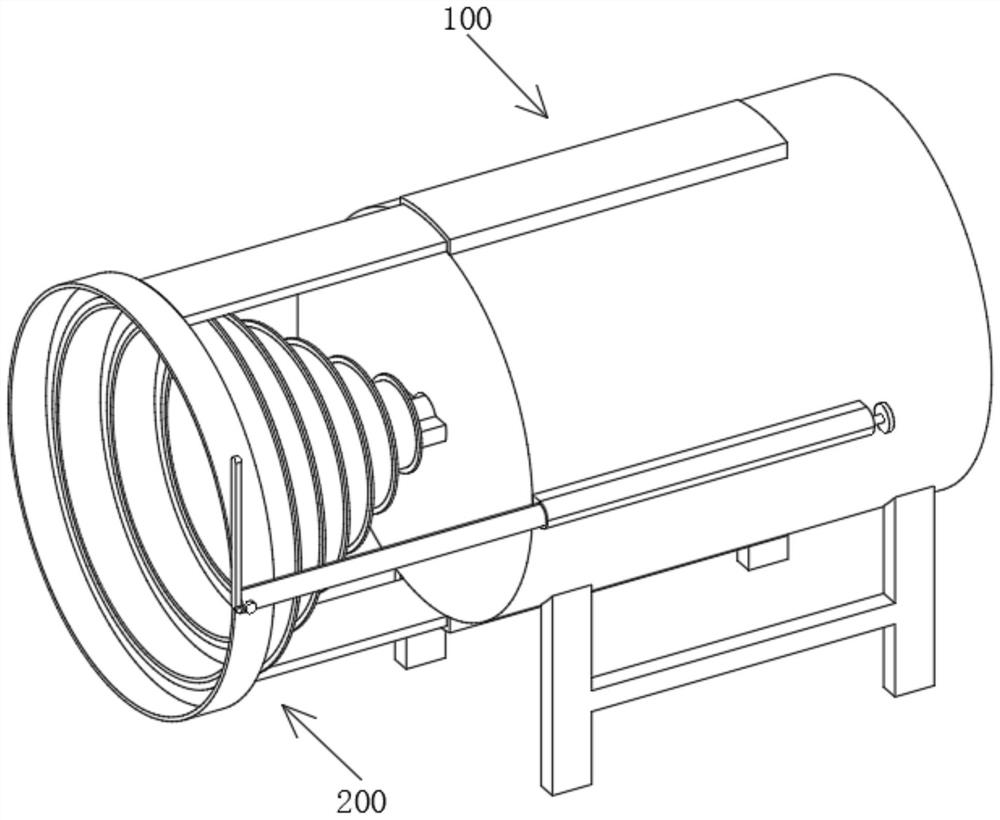
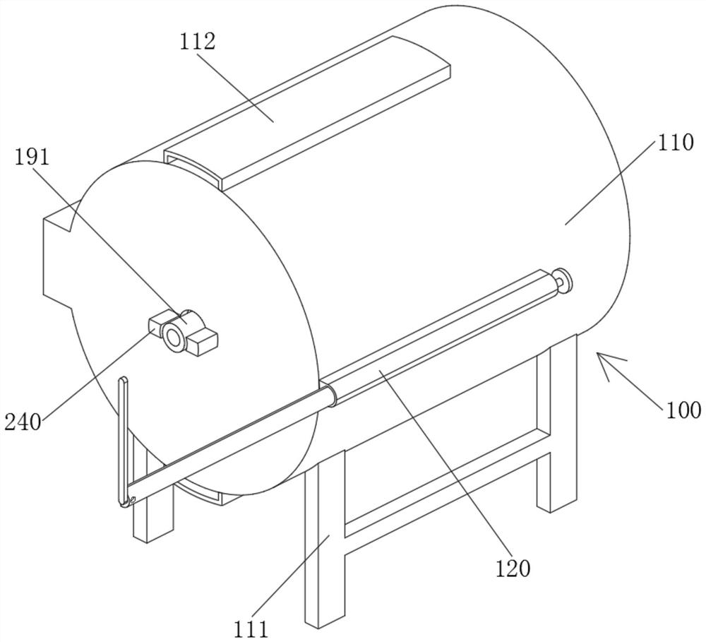
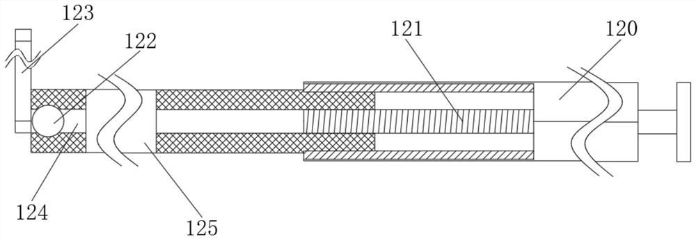
[0032] see Figure 1-11 As shown, a blanking device for automatic steel bar forming equipment includes a conveying module 100, the conveying module 100 is fixedly connected with a carding module 200, the conveying module 100 includes a housing 110, the housing 110 is fixedly connected with the carding module 200, and the housing 110 The inner surface is fixedly connected with the fixed plate 140 and the fixed ring 150, the side of the fixed plate 140 is rotatably connected with the...


PUM


Abstract

The invention relates to the technical field of steel bar discharging, in particular to a discharging device for steel bar automatic forming equipment. The discharging device comprises a conveying module, the conveying module is fixedly connected with an arranging module, the conveying module comprises a shell, the shell is fixedly connected with the arranging module, the inner side face of the shell is fixedly connected with a fixing plate and a fixing ring, the side face of the fixing plate is rotationally connected with a gear ring, the inner side face of the shell is fixedly connected with a driving mechanism in transmission connection with the gear ring, and the inner side face of the fixing ring is rotationally connected with a rotating frame. In the discharging device, through engaged transmission of inner teeth of the gear ring and a second transmission gear, the driving mechanism can drive a transmission rod to rotate, the transmission rod can drive a feeding disc to rotate through a first bevel gear and a second bevel gear, and therefore steel bars are conveyed through the feeding disc; and the rotating frame can rotate at will, and therefore when the steel bars are twisted, the feeding disc can rotate along with the steel bars, the steel bars are released, the steel bars are prevented from being damaged, and use is convenient.

Description

technical field [0001] The invention relates to the technical field of steel bar blanking, in particular to a blanking device for automatic steel bar forming equipment. Background technique [0002] In the production of steel bars, in order to facilitate the use of subsequent steel bars, the length of the steel bars is usually produced longer. When in use, the steel bars are cut and shaped according to the needs. Therefore, when the steel bars are transported, the steel bars are usually rolled up and then processed. In this way, during use, it is necessary to use a straightening machine to straighten the steel bars, and when the steel bars are transported to the straightening machine through the unloading device, since most of the steel bars are scattered, when the unloading device transports the steel bars, the steel bars are easy to be Bending and twisting will cause damage to the steel bar, which is not conducive to the use of the steel bar. Contents of the invention ...

Claims


Application Information

Patent Timeline
Patent Type & Authority Applications(China)
IPC IPC(8): B21F1/02B21F23/00
CPCB21F1/02B21F23/00
Inventor 陈永康陈梓睿陈学玲陈媛媛
Owner 陈永康
Why Eureka
Try Eureka