Eureka AIR delivers breakthrough ideas for toughest innovation challenges, trusted by R&D personnel around the world.

Noise reduction type C-shaped contact rail supporting device

A technology of supporting device and contact rail, which is applied in power rails, transportation and packaging, power supply lines, etc., can solve the problems of difficulty in improving the installation accuracy of contact rails, loss of support for the rail body, and low vibration damping, so as to reduce installation costs and reduce Frictional resistance, the effect of reducing the wear of the rail body

Active Publication Date: 2021-11-05
湖南星光速流科技有限责任公司
View PDF9 Cites 1 Cited by
  • Summary
  • Abstract
  • Description
  • Claims
  • Application Information

AI Technical Summary

Problems solved by technology

[0003]The existing C-shaped rail support structure of the maglev express line is described in detail in the patent application number CN201810020284.9. The main feature of its structure is that it is screwed with the insulator The screw rods are connected in series with the clips and limiters that extend into the C-shaped groove of the rail body and are tightened with nuts to clamp the C-shaped rail. The tightness of the clamping is adjusted by adding or subtracting gaskets with low efficiency; the rail body is extruded There are errors in profile, rail C-shaped groove and wall thickness, and the gap between clamps, limiters and rail body must ensure the largest wall thickness and the smallest C-shaped rail groove width, and the rail body expands and contracts with heat and cold It can freely stretch and slide, and there are gaps and unevenness between the clamps, limiters and rail body at each support point, which makes it difficult to improve the installation accuracy of the contact rail and the vibration damping of each support point to the rail body is very small, and the existence of support gaps , even if it is not at the rail joint, when running at high speed, when the flow-collecting shoe of the vehicle-mounted current collector passes through each support point, the contact pressure of the shoe-rail will also cause impact noise between the rail body and the support point clip; also, here The structural clamp has no relative rotation locking structure relative to the insulator, so that after long-term operation, the clamp is gradually pushed away from its working position in the expansion and contraction of the contact rail cycle. In severe cases, even the T-shaped clamp is affected by shock vibration Will deflect from vertical support to horizontal, causing the rail to lose support completely

Method used


Image

  • Noise reduction type C-shaped contact rail supporting device
  • Noise reduction type C-shaped contact rail supporting device
  • Noise reduction type C-shaped contact rail supporting device

Examples


Embodiment Construction

[0056] The following will clearly and completely describe the technical solutions in the embodiments of the present invention with reference to the accompanying drawings in the embodiments of the present invention. Obviously, the described embodiments are only part of the embodiments of the present invention, not all of them. Based on the embodiments of the present invention, all other embodiments obtained by persons of ordinary skill in the art without creative efforts fall within the protection scope of the present invention.

[0057] It should be noted that all directional indications (such as up, down, left, right, front, back...) in the embodiments of the present invention are only used to explain the relationship between the components in a certain posture (as shown in the accompanying drawings). Relative positional relationship, movement conditions, etc., if the specific posture changes, the directional indication will also change accordingly.

[0058] In addition, in t...


PUM


Abstract

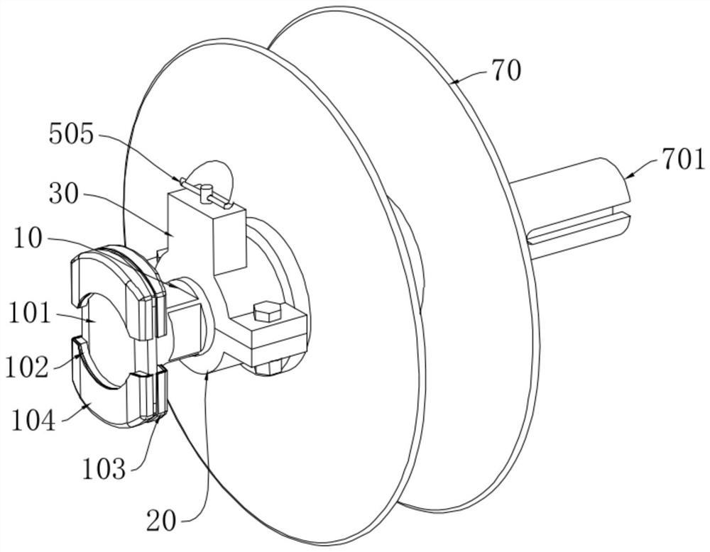
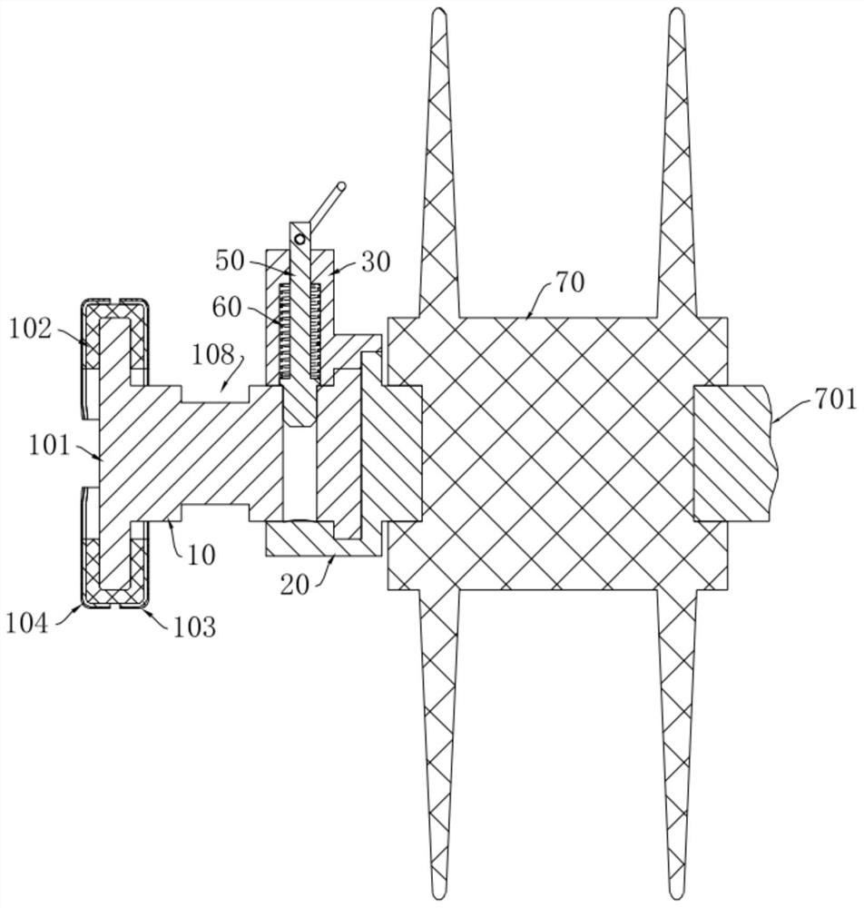
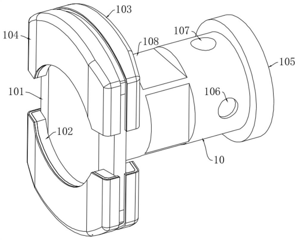
The invention discloses a noise reduction type C-shaped contact rail supporting device which comprises a clamping head mechanism, a mounting mechanism, a locking mechanism and an insulating mechanism, and the mounting mechanism is arranged at one end of the insulating mechanism; the clamping head mechanism is provided with a clamping head assembly, the length of the long side of the clamping head assembly is larger than the height of the notch of the C-shaped contact rail, and the length of the short side of the clamping head assembly is smaller than the height of the notch of the C-shaped contact rail. The clamping head mechanism has a first state and a second state. When the clamping head mechanism is in the first state, the long edge of the clamping head assembly is perpendicular to the groove height direction of the C-shaped contact rail. When the clamping head mechanism is in the second state, the long edge of the clamping head assembly is parallel to the groove height direction of the C-shaped contact rail; the locking mechanism is arranged on the mounting mechanism and movably connected with the clamping head mechanism so as to be used for locking the clamping head mechanism to be in the first state or the second state. The device can be in self-adaptive contact with the machining error size of the C-shaped groove of the strand rail body, zero-clearance fit supporting of the rail body is achieved, and the phenomenon that the clamping head assembly swings and deviates from a working position in the using process can be avoided.

Description

technical field [0001] The invention relates to the technical field of rail transit C-shaped contact rail insulation support, in particular to a noise-reducing C-shaped contact rail support device. Background technique [0002] In the field of rigid contact rail side moving contact current-supply power supply technology represented by Changsha Maglev Express Line, the C-shaped contact rail is easy to achieve high contact rail installation accuracy with appropriate side stiffness, and the rear part of the C-shaped rail The C-shaped groove is used as the installation support point of the C-shaped contact rail, which makes the cross-sectional size of the charged body of the contact rail small, which is conducive to reducing the installation space size requirements of the contact rail. Compared with the I-shaped rail, the C-shaped contact rail has technical advantages. However, the maglev train lines such as the Changsha Maglev Express Line still have noise from shoe-rail contac...

Claims


Application Information

Patent Timeline
Patent Type & Authority Applications(China)
IPC IPC(8): B60M1/30
CPCB60M1/307
Inventor 陈革
Owner 湖南星光速流科技有限责任公司
Why Eureka
Eureka Blog
Learn More