Angle-adjustable circular glass cutting device
A glass cutting and adjustable technology, used in glass cutting devices, glass manufacturing equipment, manufacturing tools, etc., can solve the problems of inability to adjust the cutting angle, irregular material cutting, etc., and achieve the effect of improving production efficiency and improving the scope of application
- Summary
- Abstract
- Description
- Claims
- Application Information
AI Technical Summary
Problems solved by technology
Method used
Image

Examples
Embodiment 1
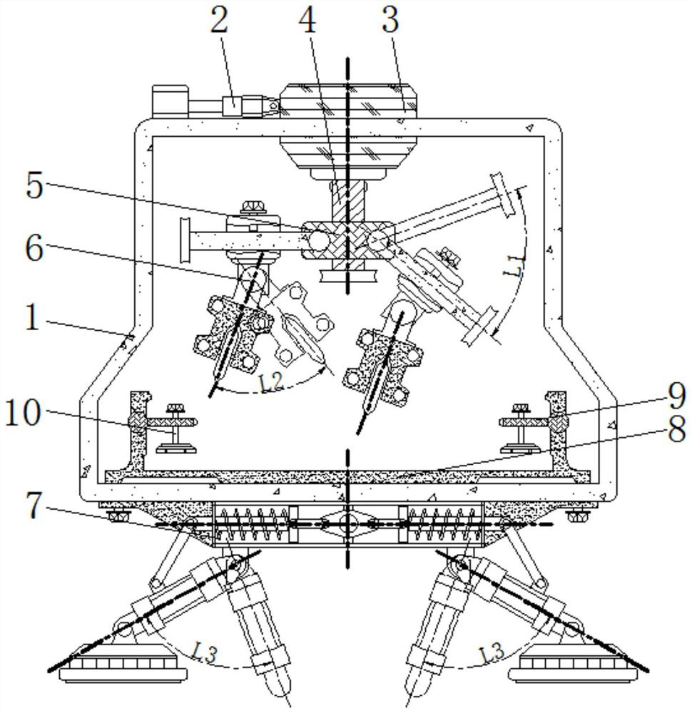
[0024] see figure 1 , figure 2 , the top of the device box 1 is welded with a hydraulic rod 2, the side of the hydraulic rod 2 is welded with a slider 3, the bottom of the slider 3 is rotatably connected with a drive rod 4, the periphery of the drive rod 4 is sleeved with a sliding sleeve 5, and the hydraulic rod 2 Welded on the left side of the top of the device box 1 in a horizontal state, and welded with the slider 3, the slider 3 is slidably connected to the top of the device box 1, a part of the slider 3 is placed inside the device box 1 and rotates with the drive rod 4 Connected, the driving rod 4 is rotated and connected to the bottom of the slider 3 in a vertical state, the inside of the sliding sleeve 5 is provided with threads, and is compatible with the threads on the periphery of the driving rod 4;
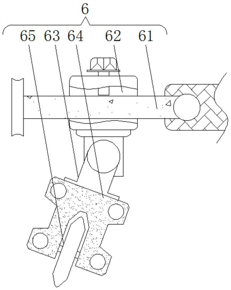
[0025] The front of the sliding sleeve 5 is provided with a cutting mechanism 6, the cutting mechanism 6, the cutting mechanism 6 includes a swing rod 61, the limit ...
Embodiment 2
[0029] see figure 1 , image 3 , the top of the device box 1 is welded with a hydraulic rod 2, the side of the hydraulic rod 2 is welded with a slider 3, the bottom of the slider 3 is rotatably connected with a drive rod 4, the periphery of the drive rod 4 is sleeved with a sliding sleeve 5, and the hydraulic rod 2 Welded on the left side of the top of the device box 1 in a horizontal state, and welded with the slider 3, the slider 3 is slidably connected to the top of the device box 1, a part of the slider 3 is placed inside the device box 1 and rotates with the drive rod 4 Connected, the driving rod 4 is rotated and connected to the bottom of the slider 3 in a vertical state, the inside of the sliding sleeve 5 is provided with threads, and is compatible with the threads on the periphery of the driving rod 4;
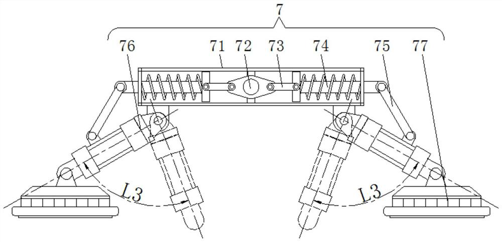
[0030] The front of sliding sleeve 5 is provided with cutting mechanism 6, and the bottom of device box 1 is provided with elevating mechanism 7, and elevating mechan...
Embodiment 3
[0034] see Figure 1-3 , the top of the device box 1 is welded with a hydraulic rod 2, the side of the hydraulic rod 2 is welded with a slider 3, the bottom of the slider 3 is rotatably connected with a drive rod 4, the periphery of the drive rod 4 is sleeved with a sliding sleeve 5, and the hydraulic rod 2 Welded on the left side of the top of the device box 1 in a horizontal state, and welded with the slider 3, the slider 3 is slidably connected to the top of the device box 1, a part of the slider 3 is placed inside the device box 1 and rotates with the drive rod 4 Connected, the driving rod 4 is rotated and connected to the bottom of the slider 3 in a vertical state, the inside of the sliding sleeve 5 is provided with threads, and is compatible with the threads on the periphery of the driving rod 4;
[0035]The front of the sliding sleeve 5 is provided with a cutting mechanism 6, the cutting mechanism 6, the cutting mechanism 6 includes a swing rod 61, the limit sleeve 62 i...
PUM
 Abstract
Description
Claims
Application Information
 - R&D
- Intellectual Property
- Life Sciences
- Materials
- Tech Scout
- Unparalleled Data Quality
- Higher Quality Content
- 60% Fewer Hallucinations
Browse by: Latest US Patents, China's latest patents, Technical Efficacy Thesaurus, Application Domain, Technology Topic, Popular Technical Reports.
© 2025 PatSnap. All rights reserved.Legal|Privacy policy|Modern Slavery Act Transparency Statement|Sitemap|About US| Contact US: help@patsnap.com