
Automatic diagnosis method and device for indoor unit temperature sensors and multi-split air conditioner

A temperature sensor and automatic diagnosis technology, which is applied to the automatic diagnosis of indoor unit temperature sensors and the field of multi-connected air conditioners, can solve the problems of inaccurate temperature acquisition, damaged temperature sensor leads, unreasonable parameters, etc., and achieve flexible methods and improve maintenance. Good efficiency and applicability

Inactive Publication Date: 2021-11-05
NINGBO AUX ELECTRIC +1
View PDF0 Cites 0 Cited by
  • Summary
  • Abstract
  • Description
  • Claims
  • Application Information

AI Technical Summary

Problems solved by technology

[0003] Since the indoor units of multi-connected air conditioners are distributed in different rooms, and most of them are hidden installations, it is not easy to overhaul
[0004] When the temperature collected by the temperature sensor of the indoor unit is inaccurate, it will seriously affect the normal operation of the air conditioner
For example, the position of the temperature sensor is reversed, the temperature sensor falls out of the fixing slot, or the lead wire of the temperature sensor is damaged, etc., which will lead to inaccurate temperature collection, resulting in poor air conditioner operation effect or unreasonable parameters, or even the air conditioner cannot operate. Sexuality and user experience have a certain impact

Method used


Image

  • Automatic diagnosis method and device for indoor unit temperature sensors and multi-split air conditioner
  • Automatic diagnosis method and device for indoor unit temperature sensors and multi-split air conditioner
  • Automatic diagnosis method and device for indoor unit temperature sensors and multi-split air conditioner

Examples


Embodiment 1

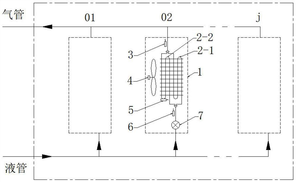
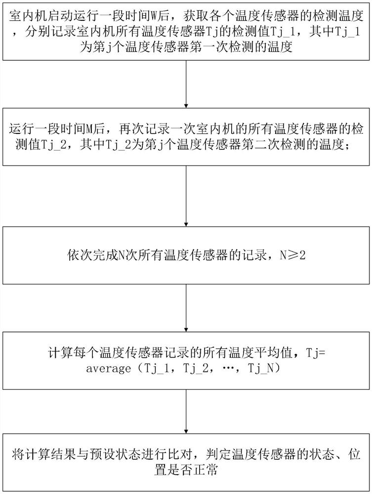
[0061] Such as Figure 1~4 As shown, the present invention discloses an automatic diagnosis method for the temperature sensor of the indoor unit. The indoor unit is provided with several temperature sensors, and the several temperature sensors can detect the temperature of at least two different positions of the heat exchanger. The diagnosis method Include the following steps:

[0062] S1: After the indoor unit starts and runs for a period of time W, obtain the detection temperature of each temperature sensor, and record the detection values ​​Tj_1 of all temperature sensors Tj of the indoor unit respectively, where Tj is the temperature of the jth temperature sensor;

[0063] S2: After running for a period of time M, record the detection values ​​Tj_2 of all temperature sensors of the indoor unit again, where Tj is the temperature of the jth temperature sensor;

[0064] S3: Complete the records of all temperature sensors N times in sequence, N≥2;

[0065] S4: Calculate the ...

Embodiment 2

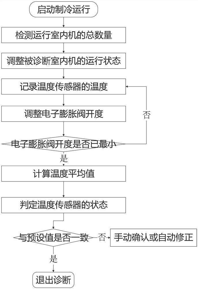
[0104] The invention discloses an automatic diagnosis method of an indoor unit temperature sensor, which comprises the following steps in the refrigeration mode:

[0105] Step 1: After the compressor starts running, detect the total number of indoor units, and automatically obtain the address of each indoor unit; diagnose the temperature sensors of the indoor units in sequence according to the address sequence of the indoor units, for example, from small to large.

[0106] Step 2: Set the minimum temperature of the indoor unit that needs to be diagnosed by the temperature sensor, usually 16°C, adjust the air guide door to the maximum opening, and adjust the indoor fan to the highest wind speed.

[0107] This setting ensures sufficient heat exchange of the indoor unit, on the one hand, it is beneficial to improve the detection accuracy of the temperature sensor, and on the other hand, it is beneficial to obtain the temperature difference of the temperature sensor.

[0108] Step...

Embodiment 3

[0117] The invention discloses an automatic diagnosis method of an indoor unit temperature sensor, which comprises the following steps in the heating mode:

[0118] When running in heating mode, perform synchronous diagnosis on the indoor unit, among which:

[0119] Step 1: After the compressor starts running, set the maximum temperature for the indoor unit that requires temperature sensor diagnosis, usually 30°C, adjust the air guide door to the maximum opening, and adjust the indoor fan to the highest wind speed to ensure sufficient heat exchange of the indoor unit.

[0120] Step 2: After continuous W time, if the frequency change of the compressor ≤ ΔF, the opening change of the electronic expansion valve of the indoor unit ≤ ΔV, and the speed of the outdoor fan remains unchanged, it is judged that the air conditioner unit has been running stably, and record this When is the temperature Tj_1 detected by the temperature sensors of all indoor units, where Tj is the temperatur...


PUM


Abstract

The invention provides an automatic diagnosis method and device for indoor unit temperature sensors and a multi-split air conditioner. According to the automatic diagnosis method for the indoor unit temperature sensors, the plurality of temperature sensors are arranged on an indoor unit, and the automatic diagnosis method for the indoor unit temperature sensors comprises the following steps that S1, after the indoor unit is started and operates for a period of time W, the detection temperature Tj_1 of each temperature sensor is obtained; S2, after the indoor unit operates for the period of time M, the detection values Tj_2 of all the temperature sensors of the indoor unit are recorded again; S3, recording of all the temperature sensors is completed N times in sequence, wherein N is larger than or equal to 2; S4, an average value of all temperatures recorded by each temperature sensor is calculated; and S5, a calculation result is compared with a preset state, and whether the state and the position of the temperature sensors are normal or not is judged. Through automatic diagnosis of the air conditioner, the abnormity of the temperature sensors can be quickly, efficiently and timely found, and under the condition that equipment and cost are not increased, the maintenance efficiency of the indoor unit is improved, and the operation reliability of the air conditioner is improved.

Description

technical field [0001] The invention relates to the technical field of air conditioning, in particular to an automatic diagnosis method and device for an indoor unit temperature sensor and a multi-connected air conditioner. Background technique [0002] The indoor unit of the multi-connected air conditioner has multiple temperature sensors to collect the temperature at different positions of the heat exchanger, which is used to calculate key parameters such as subcooling and superheating. [0003] Because the indoor units of multi-connected air conditioners are distributed in different rooms, and most of them are hidden installations, it is not easy to overhaul. [0004] When the temperature collected by the temperature sensor of the indoor unit is inaccurate, it will seriously affect the normal operation of the air conditioner. For example, the position of the temperature sensor is reversed, the temperature sensor falls off from the fixing slot, or the lead wire of the tem...

Claims


Application Information

Patent Timeline
Patent Type & Authority Applications(China)
IPC IPC(8): F24F11/38F24F11/61F24F11/64F24F11/65F24F11/84F24F11/86F24F11/88F24F110/10
Inventor 邓赛峰刘合心宋磊
Owner NINGBO AUX ELECTRIC
Learn More