

Photovoltaic direct current surge protection device
A technology of surge protection and surge protector, applied in emergency protection circuit devices, emergency protection circuit devices for limiting overcurrent/overvoltage, circuit devices, etc., can solve problems such as low work efficiency and achieve practicability High, to avoid separation, to achieve the effect of effective limit
- Summary
- Abstract
- Description
- Claims
- Application Information
AI Technical Summary
Problems solved by technology
Method used
Image

Examples
Embodiment 1
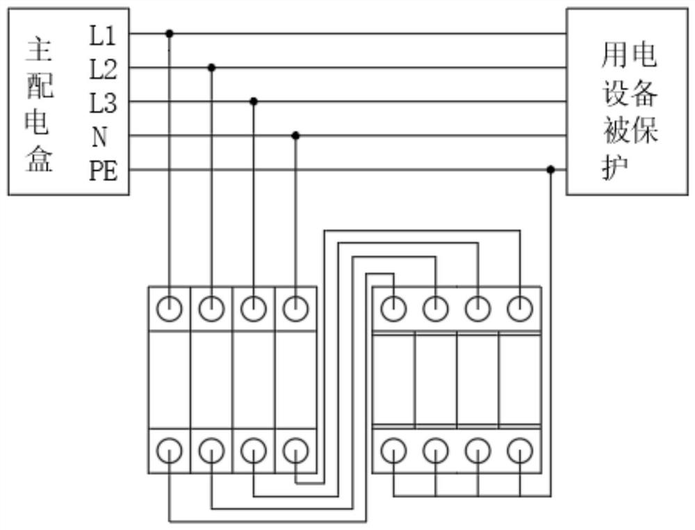
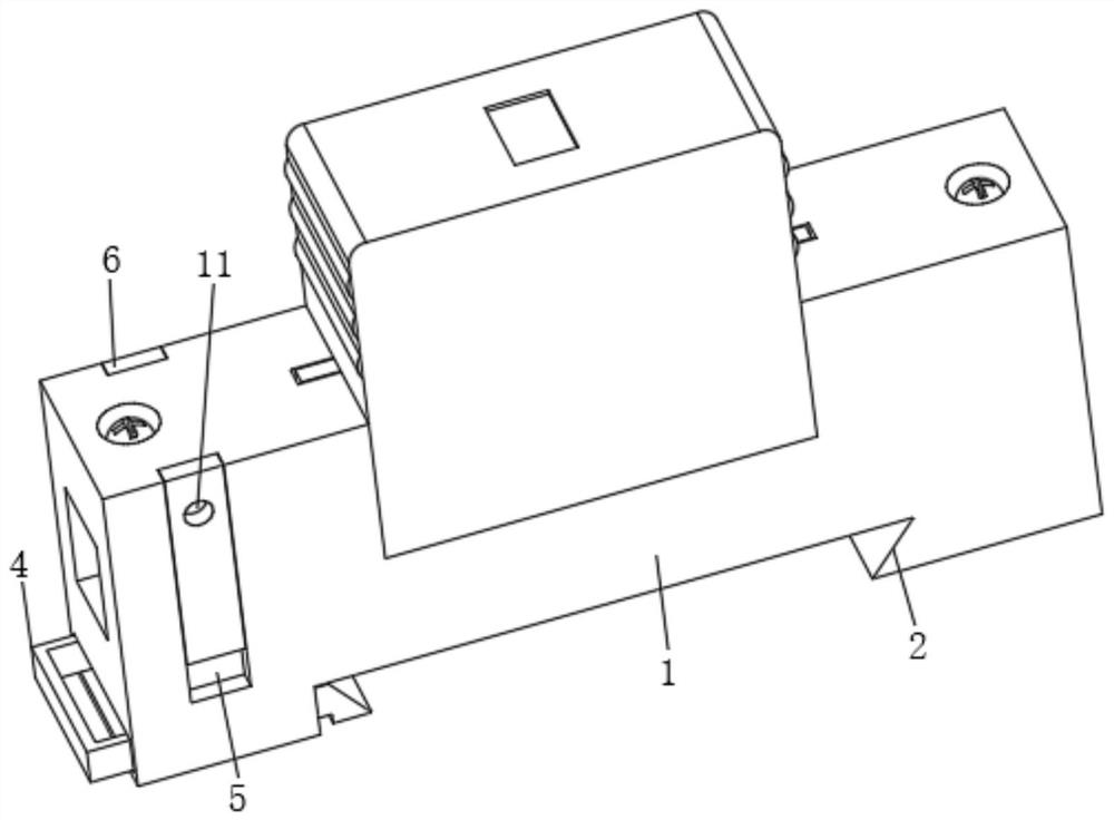
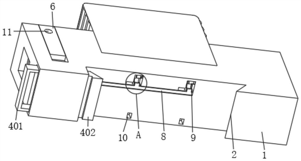
[0045] see figure 1 , figure 2 , Figure 5 , Figure 10 and Figure 11 , the embodiment of the present invention provides a photovoltaic DC surge protection device: including a surge protector 1 and an oblique protrusion 2 on the lower side thereof, the front and rear sides of the surge protector 1 pass through square grooves 5 on both sides A slide bar 6 is slidably installed, and the other side below the surge protector 1 is slidably installed with a clamping assembly 4 that cooperates with the oblique protrusion 2 to fix the surge protector 1. The inside of the surge protector 1 is provided with a The moving component 7 of the clamping component 4 is fixedly connected to one of the sliding bars 6 through the gap 15 opened on the surge protector 1. The inside of the surge protector 1 is fixedly installed with a power supply component 3. The power supply component 3 Attach to the opposite sides of the two slide bars 6 respectively. Among them, the surge protector 1 is a...
Embodiment 2
[0050] see figure 2 , Figure 9 and Figure 10 , on the basis of Embodiment 1, the front and rear sides of the surge protector 1 are provided with placement grooves 16, the inside of the placement groove 16 is provided with a rectangular block 17, the side wall of the rectangular block 17 is fixedly connected with the slide bar 6, and the rectangular block 17 A first spring 14 is fixedly installed between the bottom of the block 17 and the groove wall of the placement groove 16 .
[0051] In this embodiment, preferably: in the initial state, the rectangular block 17 is located in the middle of the placement groove 16; the placement groove 16 provided with the rectangular block 17 can ensure that the slide bar 6 slides up and down stably, and the first spring provided 14 has played the effect of supporting rectangular block 17 and slide bar 6; initial position.
[0052] As a further improvement of this embodiment: in actual use, a first spring 14 can also be installed betw...
Embodiment 3
[0054] see Figure 5 and Figure 6 , on the basis of the second embodiment, the energization component 3 includes a metal joint 301, the metal joint 301 is fixedly connected with the surge protector 1, and the inside of the metal joint 301 is slidably installed with two metal guide posts 302, and the two metal guide posts 302 A second spring 303 is fixedly mounted on the opposite side of each other.
[0055] In this embodiment, it is preferable to use the metal joint 301 and the metal guide post 302, so that after the wire is connected and fixed to the metal joint 301, the circuit conduction can be realized, and the surge protector 1 can work normally, and the metal joint 301 can also The electricity is transmitted to the metal guide posts 302 .
PUM
 Abstract
Description
Claims
Application Information