Part purging equipment

A technology for purging equipment and parts, applied in cleaning methods and utensils, chemical instruments and methods, and cleaning methods using gas flow, etc. Low efficiency and other problems, to achieve the effect of strong practicability, improved work efficiency and good use effect

Pending Publication Date: 2021-11-09
SUZHOU KAIHUI RAILWAY ELECTROMECHANICAL CO LTD
View PDF0 Cites 0 Cited by
  • Summary
  • Abstract
  • Description
  • Claims
  • Application Information

AI Technical Summary

Problems solved by technology

[0002] In the production process of mechanical engineering, many parts are used. Among them, the dust in the air is usually attached to such parts during long-term use, which will affect the performance of parts and require regular cleaning.
[0003] However, the working efficiency of the existing bl

Method used


Image

  • Part purging equipment
  • Part purging equipment
  • Part purging equipment

Examples


Embodiment Construction

[0018] The following will clearly and completely describe the technical solutions in the embodiments of the present invention with reference to the accompanying drawings in the embodiments of the present invention. Obviously, the described embodiments are only some, not all, embodiments of the present invention. Based on the embodiments of the present invention, all other embodiments obtained by persons of ordinary skill in the art without making creative efforts belong to the protection scope of the present invention.

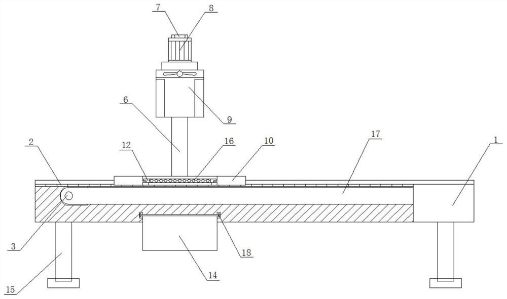
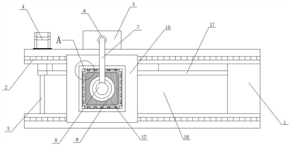
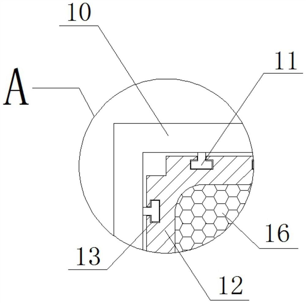
[0019] see Figure 1-3 , the present invention provides a technical solution: a parts purging equipment, including a mounting base 1, the upper end of the mounting base 1 is equipped with guide rails 2 on the front and rear sides, the guide rails 2 are connected and installed with a rotating rod 3, and the rear end surface of the rotating rod 3 Run through the rear side wall of the mounting base 1 and connect and install the rotating motor 4, and the rotating ...


PUM


Abstract

The invention discloses part purging equipment. The part purging equipment comprises a mounting base; guide rails are mounted on the front and back sides of the upper end surface of the mounting base; a rotating rod is connected and mounted between the guide rails; the back end surface of the rotating rod penetrates through the back side wall of the mounting base, and is connected and provided with a rotating motor; a driving device is mounted on the right side of the rotating motor and on the mounting base; an output end of the driving device is connected and provided with purging equipment; a bearing plate is slidably mounted on the upper end surfaces of the guide rails; limiting blocks are welded and mounted on the side wall of an inner ring of the bearing plate at equal intervals; placing frames are matched and mounted on the limiting blocks; multiple limiting grooves corresponding to the limiting blocks are formed in the side walls of outer rings of the placing frames; a dust collecting bag is mounted in the mounting base and aligned to the purging equipment; and support rods are welded and mounted on two sides of the bottom of the mounting base. The part purging equipment is reasonable in structural design, realizes improvement, and facilitates improvement of the working efficiency.

Description

technical field [0001] The invention relates to the technical field of improvement related to parts purging equipment, in particular to a parts purging equipment. Background technique [0002] In the production process of mechanical engineering, many parts are used. Among them, such parts usually adhere to the dust in the air during long-term use, which will affect the performance of the parts and require regular cleaning. [0003] However, the working efficiency of the existing blowing equipment is low, and it is necessary to manually place the parts in the work area one by one for the blowing operation. The dust left by the blowing will affect the health of the operators. Dust is not treated centrally, therefore, it is necessary to design a new type of parts purging equipment. Contents of the invention [0004] The object of the present invention is to provide a parts purging device to solve the problems raised in the background art above. [0005] In order to achieve ...

Claims


Application Information

Patent Timeline
IPC IPC(8): B08B5/02B08B13/00
CPCB08B5/02B08B13/00
Inventor 冉瑞志
Owner SUZHOU KAIHUI RAILWAY ELECTROMECHANICAL CO LTD
Why Eureka
Try Eureka