
Direct-current electric hand riveter

A riveting gun, electric technology, applied in the direction of engine components, engine lubrication, mechanical equipment, etc., can solve the problems of high noise, laborious use, user fatigue efficiency, etc., to achieve easy installation and disassembly, reduce wear, and improve service life. Effect

Pending Publication Date: 2021-11-09
刘海林
View PDF27 Cites 1 Cited by
  • Summary
  • Abstract
  • Description
  • Claims
  • Application Information

AI Technical Summary

Problems solved by technology

Normally, manual riveting guns are laborious to use, and are prone to fatigue and low efficiency in frequent and continuous riveting work; pneumatic riveting guns have the advantages of fast speed and high pulling force, but they must have an air source and are noisy , unable to work in the field; electric riveting guns, especially hand-held electric riveting guns, are easy to carry and can be used in field operations, and are widely used;
[0004] But in the prior art of using the electric riveting gun, at least the following problems have not been effectively improved: 1. When the electric riveting gun is used for high-altitude operations in the field, the waste core produced by the electric riveting gun is easy to Falling from a high place has caused object strikes to the workers on the ground below, which is easy to cause personal danger to the workers on the ground below; 2. When the electric riveting gun is working, the motor needs to rotate forward and reverse frequently, so that the main transmission in the riveting gun The components need to move forward and backward frequently, resulting in greater wear and tear, which will easily reduce the service life of the electric riveting gun

Method used


Image

  • Direct-current electric hand riveter
  • Direct-current electric hand riveter
  • Direct-current electric hand riveter

Examples


Embodiment Construction

[0042] The following will clearly and completely describe the technical solutions in the embodiments of the present invention with reference to the accompanying drawings in the embodiments of the present invention. Obviously, the described embodiments are only some, not all, embodiments of the present invention. Based on the embodiments of the present invention, all other embodiments obtained by persons of ordinary skill in the art without making creative efforts belong to the protection scope of the present invention.

[0043] see Figure 1 to Figure 11 , the present invention provides a technical solution:

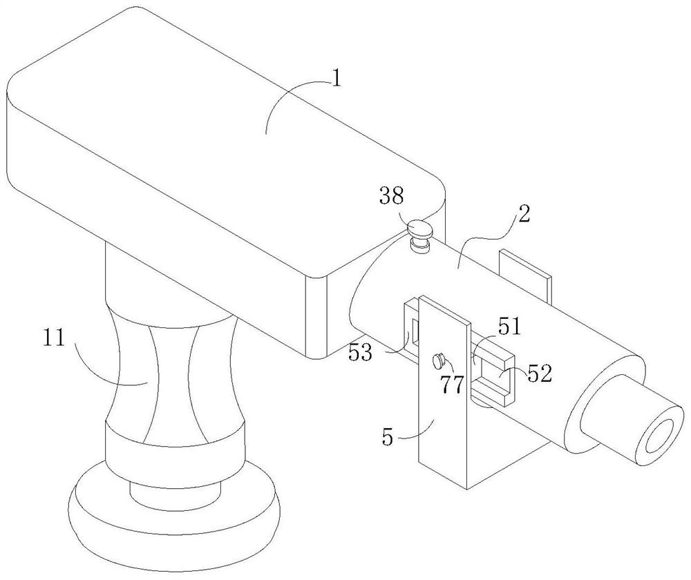
[0044] A DC electric riveting gun, comprising a gun body 1, a handle 11 is fixedly connected to the bottom of the gun body 1, a riveting mechanism 2 is fixedly connected to the right end of the gun body 1, and the inside of the riveting mechanism 2 is from left to On the right side, there are lubricating components 3 and fixing holes 4 in turn. A waste core clip 5 is mo...


PUM


Abstract

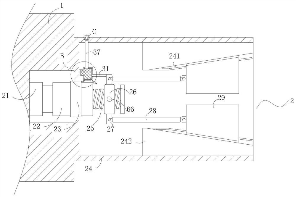
The invention relates to the technical field of hand riveters, in particular to a direct-current electric hand riveter. The direct-current electric hand riveter comprises a riveter body, a handheld part is fixedly connected to the bottom of the riveter body, a rivet pulling mechanism is fixedly connected to the right end of the riveter body, a lubricating assembly and a fixing hole are sequentially arranged in the rivet pulling mechanism from left to right, a waste core clamp is movably connected to the lower portion of the rivet pulling mechanism, an anti-clamping assembly is arranged between the rivet pulling mechanism and the waste core clamp, the anti-clamping assembly is arranged at the bottom of the rivet pulling mechanism, a clamping assembly is arranged at the movable joint of the rivet pulling mechanism and the waste core clamp, a motor rotates forwards and backwards once to drive a screw cylinder to reciprocate leftwards and rightwards once, so that a transmission rod pulls a riveting block to move leftwards and rightwards once. Due to the inclined arrangement of a T-shaped groove, when the two groups of riveting blocks move leftwards, the distance is reduced, so that a rivet is clamped and continuously pulled to move, a core rod of the rivet drives a rivet head to expand so as to plug a hole, meanwhile, the thinnest part of the core rod of the rivet is necked so as to be snapped, so that the rivet pulling action is completed.

Description

technical field [0001] The invention relates to the technical field of riveting guns, in particular to a DC electric riveting gun. Background technique [0002] Riveting gun is used for fastening and riveting of various metal sheets, pipes and other manufacturing industries. It is currently widely used in riveting of electromechanical and light industrial products such as elevators, switches, instruments, furniture, and decoration. The welding nut of the thin tube is easy to melt, and the thread is easy to slip when tapping the internal thread. It can be riveted to riveting products that do not need to tap the internal thread or weld the nut. [0003] Riveting guns can generally be divided into manual riveting guns, pneumatic riveting guns and electric riveting guns. Normally, manual riveting guns are laborious to use, and are prone to fatigue and low efficiency in frequent and continuous riveting work; pneumatic riveting guns have the advantages of fast speed and high pull...

Claims


Application Information

Patent Timeline
IPC IPC(8): B21J15/10B21J15/26B21J15/38B21J15/42F16N11/00
CPCB21J15/10B21J15/26B21J15/38B21J15/42F16N11/00Y02P70/10
Inventor 刘海林莫传旭
Owner 刘海林
Learn More