One-way ratchet wrench structure

A one-way ratchet and ratchet technology, applied in the field of wrench tools, can solve the problems of increasing the friction time of the ratchet teeth, easy collision and damage of the ratchet teeth, reducing the meshing efficiency of the stuck ratchet block and the ratchet wheel, etc. Effect

Pending Publication Date: 2021-11-09
ZHEJIANG MAXTOP TOOLS MFG CO LTD
View PDF1 Cites 0 Cited by
  • Summary
  • Abstract
  • Description
  • Claims
  • Application Information

AI Technical Summary

Problems solved by technology

[0003] Looking at the above-mentioned known structure in detail, it is not difficult to find that it still has some deficiencies. The main reasons are as follows: the known stuck ratchet block is provided with full ratchet teeth on one side of the inner arc concave, and the inner arc concave The other side section is provided with a lower and smooth sliding surface, because the angles of the ratchets are all equal, and meshed with the ratchets on the outer periphery of the ratchet, when the locking ratchet block and the ratchet want to disengage to form a When idling, the stuck ratchet needs to be pushed for a longer stroke, which increases the friction time between the ratchet teeth and cannot be disengaged quickly, resulting in wear and tear of the ratchet. In addition, the ratchet of the stuck ratchet and the The sliding surface is simultaneously engaged with the ratchets on the outer periphery of the ratchet, and the spring is arranged at the central bottom of the locking ratchet facing the center of the accommodating chamber, so that when the structure is used, the locking ratchet is Disengaging or engaging the ratchet in a straight-up and straight-down manner greatly reduces the meshing efficiency between the ratchet block and the ratchet, and at the same time causes the ratchets to easily collide and be damaged, which is not practical

Method used


Image

  • One-way ratchet wrench structure
  • One-way ratchet wrench structure
  • One-way ratchet wrench structure

Examples


Embodiment Construction

[0024] In order to have a further understanding and understanding of the purpose, features and effects of the present invention, please cooperate with the drawings to describe in detail below:

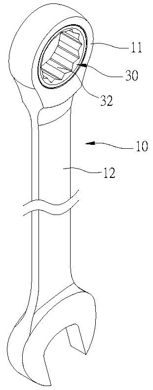
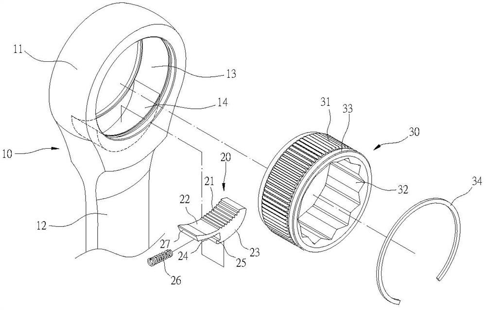
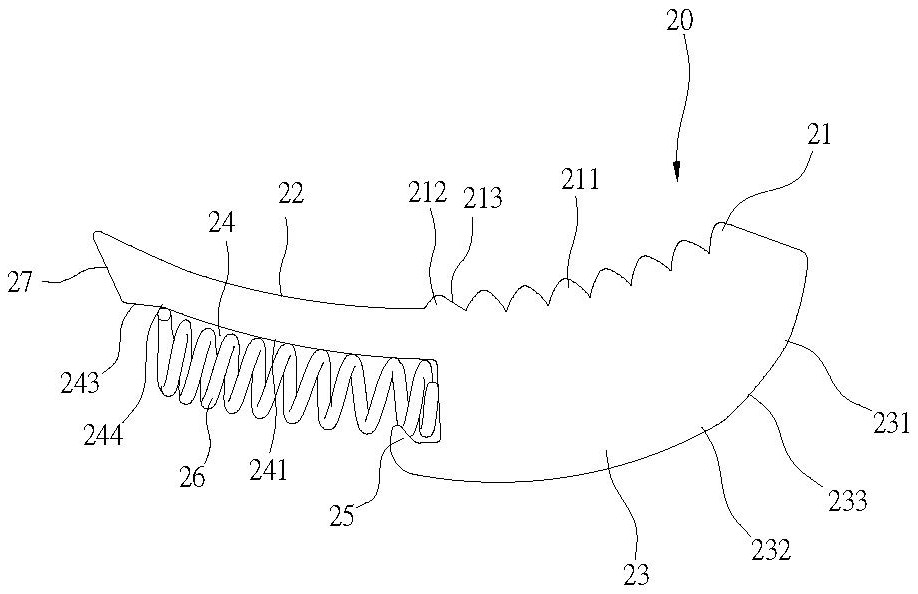
[0025] First, please see figure 1 , 2 , 3 and 4, a one-way ratchet wrench structure, which includes: a wrench body 10, a gear part 20 and a ratchet 30, the wrench body 10 has a head 11 and a handle 12, the head The part 11 is provided with an accommodating space 13, the accommodating space 13 runs through the upper and lower ends of the head 11, and the head 11 is provided with an accommodating groove 14 from the accommodating space 13 to the direction of the handle 12, and the accommodating space 13 The accommodating groove 14 communicates with the accommodating space 13 , and the accommodating groove 14 is in the shape of an arc; The end surface is concave arc-shaped, and an arc-shaped tooth section 21 and an arc-shaped section 22 are arranged on the upper end surface. Angled teet...


PUM


Abstract

The invention discloses a one-way ratchet wrench structure. The one-way ratchet wrench structure comprises a wrench body, a tooth manufacturing piece and a ratchet wheel. The wrench body is provided with containing space and a containing groove, the ratchet wheel is installed in the containing space, the tooth manufacturing piece is installed in the containing groove, a tooth section of the tooth manufacturing piece is provided with multiple equal-angle teeth and a different-angle tooth, and due to the fact that the angle of the different-angle tooth is different from the angles of the equal-angle teeth, and the different-angle tooth sinks to be lower than the equal-angle teeth, when the wrench body is twisted anticlockwise, the wrench body can be rapidly separated from the equal-angle teeth of the ratchet wheel through the different-angle tooth. A cambered surface section and the tooth section of the tooth manufacturing piece are cambered surfaces which are not concentric and abut against the periphery of the ratchet wheel at different times, through abutting of a fulcrum of the tooth manufacturing piece and center-of-gravity shift during wrench twisting, the tooth manufacturing piece can generate deflection action similar to a seesaw, and the effects that the tooth section is quickly engaged with the periphery of the ratchet wheel and slipping happens indeed are achieved.

Description

technical field [0001] The invention relates to a wrench tool, in particular to a one-way ratchet wrench structure. Background technique [0002] Known ratchet wrench structure, such as U.S. Patent No. US7444903B1, the structural improvement of the ratchet wrench No. M327769 of the Taiwan Patent Announcement Certificate No., which is composed of a wrench body, a snap ratchet block, a ratchet wheel and a limit ring One end of the wrench body is provided with a through ratchet hole groove, one side of the ratchet hole groove is provided with a limit ring rib, and the other side is provided with a ring ring groove, and the ratchet hole groove There is also a built-in arc-shaped storage chamber towards the handle; the buckle ratchet is a curved banana shape, and there are ratchets on one side of the inner arc recess, and the other part of the inner arc recess One side section is provided with a lower and flat sliding surface, and the outer arc end edge of the ratchet side is pr...

Claims


Application Information

Patent Timeline
IPC IPC(8): B25B13/46B25B23/00
CPCB25B13/46B25B23/00
Inventor 施能嘉
Owner ZHEJIANG MAXTOP TOOLS MFG CO LTD
Why Eureka
Try Eureka