Eureka AIR delivers breakthrough ideas for toughest innovation challenges, trusted by R&D personnel around the world.

Display middle frame injection mold convenient for stripping

A technology for injection molds and displays, which can be applied to household appliances, other household appliances, household components, etc., can solve the problems of difficult separation of the middle frame, deformation of the middle frame, large contact area, etc., and achieve the effect of easy separation

Pending Publication Date: 2021-11-09
苏州冬宝光电科技有限公司
View PDF0 Cites 0 Cited by
  • Summary
  • Abstract
  • Description
  • Claims
  • Application Information

AI Technical Summary

Problems solved by technology

During the injection molding production of the middle frame of the display, since the middle frame includes two parts: the bottom frame and the side frame around the bottom frame, the traditional stripping thimble can only withstand the bottom frame for stripping, and the contact area between the bottom frame and the stripping thimble Small, but the contact area between the side frame and the lower mold core is large, the middle frame is not easy to separate from the lower mold core when the thimble is stripped, and it is easy to cause the middle frame to deform

Method used


Image

  • Display middle frame injection mold convenient for stripping
  • Display middle frame injection mold convenient for stripping
  • Display middle frame injection mold convenient for stripping

Examples


Embodiment Construction

[0031] The following will clearly and completely describe the technical solutions in the embodiments of the present invention with reference to the accompanying drawings in the embodiments of the present invention. Obviously, the described embodiments are only some, not all, embodiments of the present invention. Based on the embodiments of the present invention, all other embodiments obtained by persons of ordinary skill in the art without creative efforts fall within the protection scope of the present invention.

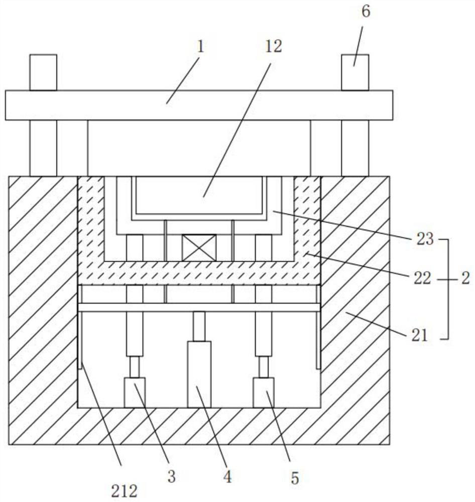
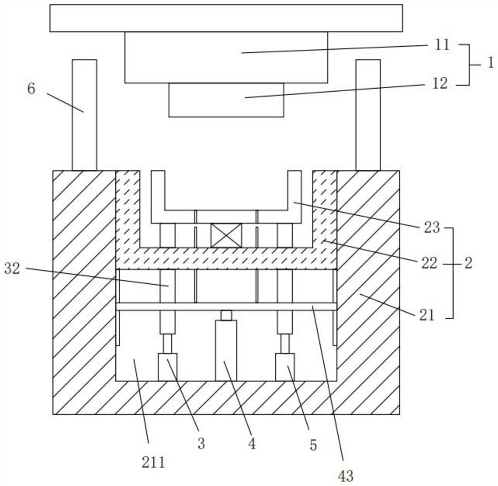
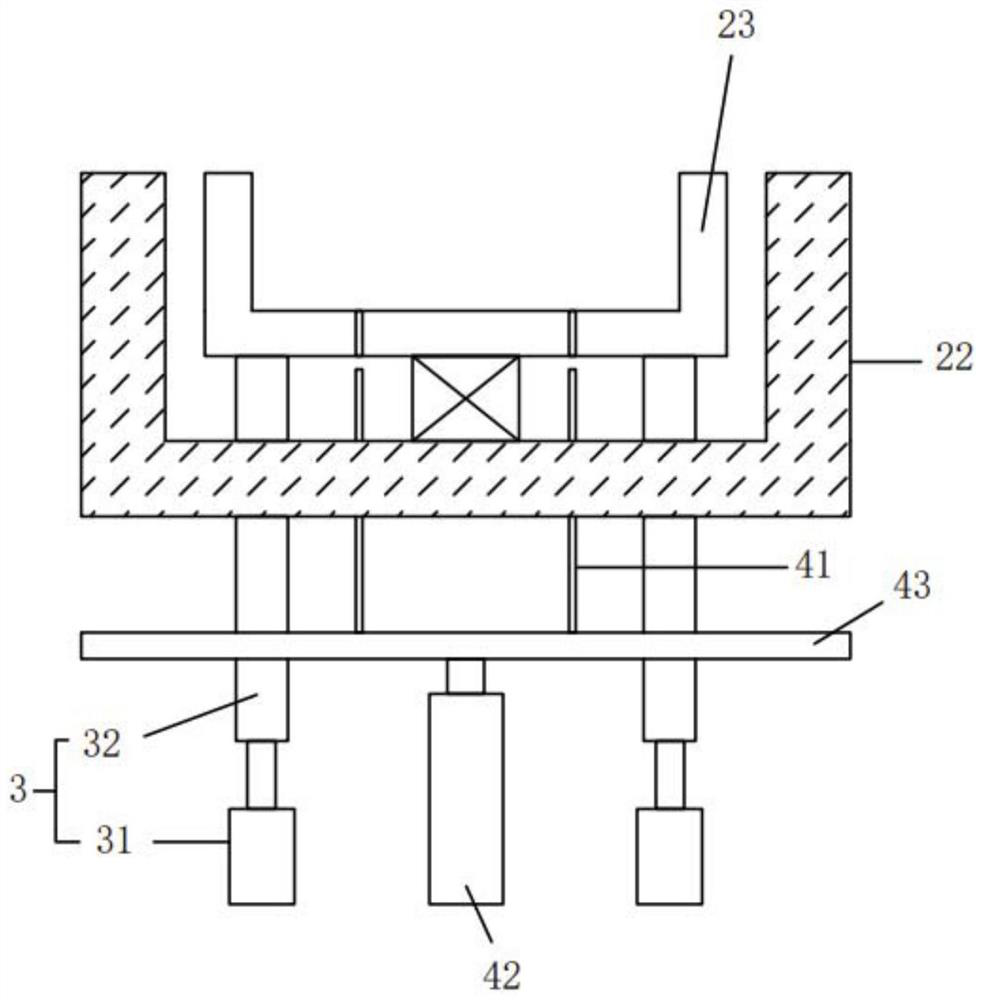
[0032] see Figure 1-3 , the present invention provides a technical solution: an injection mold for the middle frame of a display that is easy to strip, comprising:

[0033] Upper mold mechanism 1, which includes upper mold base 11 and upper mold core 12, upper mold core 12 is fixedly installed on the bottom of upper mold base 11;

[0034] The lower mold mechanism 2 comprises a base 21, a lower mold base 22 and a lower mold core 23, the lower mold base 22 is fixed...


PUM


Abstract

The invention discloses a display middle frame injection mold convenient for stripping, which comprises an upper mold mechanism and a lower mold mechanism, wherein the upper mold mechanism comprises an upper mold base and an upper mold core; and the upper mold core is fixedly mounted at the bottom of the upper mold base; the lower mold mechanism comprises a base, a lower mold base and a lower mold core; the lower mold base is fixedly mounted in an accommodating cavity of the base; the lower mold core is elastically connected into the lower mold base; the upper mold core and the lower mold core are spliced to form a forming cavity of the middle frame; a first supporting mechanism is arranged below the lower mold core and comprises a first driving device and a first supporting rod; after penetrating through the lower mold base, the first supporting rod is abutted against the bottom of the lower mold core; a stripping mechanism is further arranged in the accommodating cavity; and an ejector pin of the stripping mechanism sequentially penetrates through the lower mold base and the lower mold core. According to the invention, compared with the prior art, the lower mold core is elastically connected into the lower mold base, and before a middle frame is jacked up by the stripping ejector pin, the lower mold core shakes, so that the middle frame is conveniently separated from the lower mold core, and stripping of the ejector pin is smoother.

Description

technical field [0001] The invention belongs to the technical field of material stripping of injection molded parts, in particular to an injection mold for a middle frame of a display which is easy to strip. Background technique [0002] Injection molding is an industrial product production method, which uses thermoplastic or thermosetting materials to make plastic products of various shapes using plastic molding molds. [0003] Currently, display components are mainly produced through injection molds. During the injection molding production of the middle frame of the display, since the middle frame includes two parts: the bottom frame and the side frame around the bottom frame, the traditional stripping thimble can only withstand the bottom frame for stripping, and the contact area between the bottom frame and the stripping thimble Small, but the contact area between the side frame and the lower mold core is large, the middle frame is not easy to separate from the lower mo...

Claims


Application Information

Patent Timeline
Patent Type & Authority Applications(China)
IPC IPC(8): B29C45/26B29C45/40B29L31/34
CPCB29C45/26B29C45/4005B29L2031/3475
Inventor 李建新
Owner 苏州冬宝光电科技有限公司
Why Eureka
Eureka Blog
Learn More