Self-cleaning faucet

A faucet and self-cleaning technology, applied in the field of faucets, can solve the problems affecting people's health, affecting the effect of hand washing, reducing people's hygiene level, etc., and achieve good hand washing effect, simple and practical structure, convenient use and humanized effect

Active Publication Date: 2021-11-09
NINGBO AOLEISHI SANITARY WARE
View PDF9 Cites 0 Cited by
  • Summary
  • Abstract
  • Description
  • Claims
  • Application Information

AI Technical Summary

Problems solved by technology

[0004] Regarding the above-mentioned related technologies, the inventor believes that before using the faucet in the related technology, it is necessary to turn the handle with dirty hands to control the opening of the faucet. After use, it is necessary to turn the contaminated handle again with clean hands to Turn off the faucet, which greatly affects the effect of hand washing, reduces people's hygiene level and is easy to become a carrier of some infectious diseases, affecting people's health

Method used


Image

  • Self-cleaning faucet
  • Self-cleaning faucet
  • Self-cleaning faucet

Examples


Embodiment 1

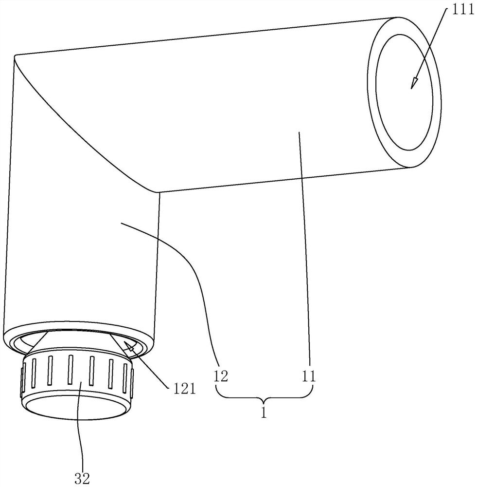
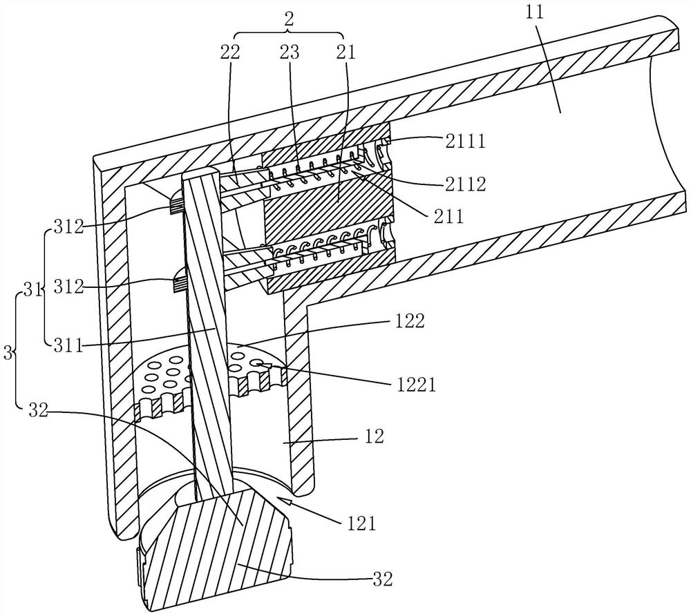
[0036] refer to figure 1 and figure 2 A self-cleaning water faucet includes a faucet body 1, a valve core 2 and a control assembly 3. The faucet body 1 includes an integrally formed and connected water inlet pipe section 11 and an outlet pipe section 12. The axis of the water inlet pipe section 11 is connected to the water outlet pipe section 12. The axis of the water inlet pipe section 11 is vertical, the end of the water inlet pipe section 11 away from the water outlet pipe section 12 is the water inlet 111, and the end of the water outlet pipe section 12 away from the water inlet pipe section 11 is the water outlet 121.

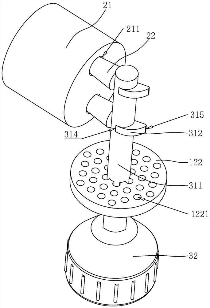
[0037] refer to figure 1 and figure 2, the valve core 2 is located in the water inlet pipe section 11, the valve core 2 includes a valve body 21, a plug 22 and a spring 23, the valve body 21 is cylindrical, and the valve body 21 is coaxially installed in the water inlet pipe section 11, the valve body 21 The outer diameter is sealed with the inner dia...

Embodiment 2

[0048] refer to Figure 4 The difference between Embodiment 2 and Embodiment 1 lies in the difference of the driving member 31. The driving member 31 also includes two second abutting blocks 313, and the structure and size of the second abutting block 313 and the first abutting block 312 are exactly the same. , each second abutting block 313 is installed in cooperation with a plug 22 respectively.

[0049] refer to Figure 4 , the second abutment block 313 is welded to the side wall of the drive rod 311, and the second abutment block and the first abutment block 312 are located at the same height in the axial direction of the drive rod 311 in one-to-one correspondence. When any second abutment block When the closed position 315 of 313 abuts against the matched plug 22 , the open position 314 of the other second abutting block 313 abuts against the matched plug 22 .

[0050] The implementation principle of Embodiment 2 is: when cold water needs to flow out of the faucet, turn...


PUM


Abstract

The invention relates to a self-cleaning faucet and relates to the field of faucets. The self-cleaning faucet comprises a faucet body, a valve element and a control assembly, the faucet body comprises a water inlet pipe section and a water outlet pipe section which are integrally formed, the valve element is located in the water inlet pipe section, the control assembly comprises a driving part and a rotary knob, the driving part is located in the water outlet pipe section, and the driving part is used for driving the valve element to be opened and closed; and the rotary knob is positioned at a water outlet of the water outlet pipe section and is connected with the driving part. According to the self-cleaning faucet, in the hand washing process, the polluted rotary knob can also be washed clean through water flow, so that the faucet can be cleaned, the hand cannot touch dirt when the rotary knob is rotated to close the faucet after hand washing is completed, the good hand washing effect is achieved, and sanitation and health of people can be kept easily.

Description

technical field [0001] The present application relates to the field of faucets, in particular to a self-cleaning faucet. Background technique [0002] A faucet is a valve that controls the flow of water. The replacement speed of the faucet is very fast. From the old-fashioned cast iron process to the electroplated knob type, and then to the stainless steel single-temperature single-control one, many families now use stainless steel double-temperature double-control faucet, and there is also a kitchen combination type. faucet. [0003] At present, the faucet in the related art generally includes a faucet body, a valve core and a handle. The valve core is arranged inside the faucet body, and the handle is connected to the valve core to control the opening and closing of the valve core. Open and close, so that the opening and closing of the faucet can be controlled. [0004] Regarding the above-mentioned related technologies, the inventor believes that before using the fauce...

Claims


Application Information

Patent Timeline
Patent Type & Authority Applications(China)
IPC IPC(8): F16K11/16F16K1/32F16K31/524F16K31/60E03C1/04
CPCF16K11/166F16K31/52416F16K31/5245F16K31/60F16K31/605F16K1/32E03C1/0412Y02A20/411
Inventor 张伟吴文超
Owner NINGBO AOLEISHI SANITARY WARE
Why Eureka
Try Eureka