Slag salvaging machine

A slag scavenger and slag plate technology is applied in the field of slag scavenging on the metal liquid surface, which can solve the problems of human fatigue, poor human physiology, and influence.

Pending Publication Date: 2021-11-09
李想
View PDF0 Cites 0 Cited by
  • Summary
  • Abstract
  • Description
  • Claims
  • Application Information

AI Technical Summary

Problems solved by technology

[0003] In the prior art, in the prior art, the slag net is held by manual hands to carry out slag removal. Since the melting pot and the molten metal liquid surface in it are in a high temperature state, it has a bad influence on the physiology of the human body; secondly, Manual slag removal also makes the human body tired

Method used


Image

  • Slag salvaging machine
  • Slag salvaging machine
  • Slag salvaging machine

Examples


Embodiment Construction

[0024] The specific implementation manner of the present invention will be further described below in conjunction with the accompanying drawings. Wherein the same components are denoted by the same reference numerals. It should be noted that the words "front", "rear", "left", "right", "upper" and "lower" used in the following description refer to the directions in the drawings, and the words "inner" and "outer ” refer to directions towards or away from the geometric center of a particular part, respectively.

[0025] In order to make the content of the present invention more clearly understood, the technical solutions in the embodiments of the present invention will be clearly and completely described below in conjunction with the drawings in the embodiments of the present invention.

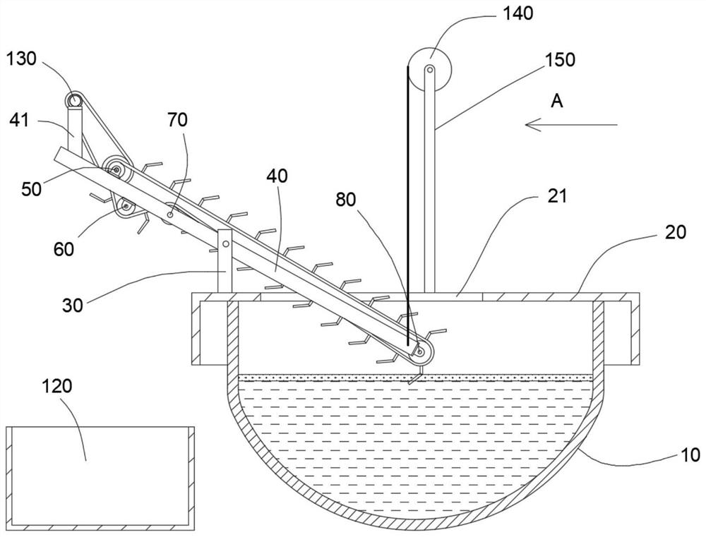
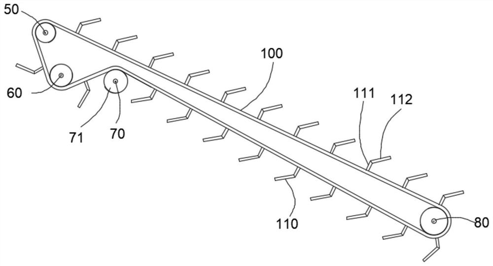
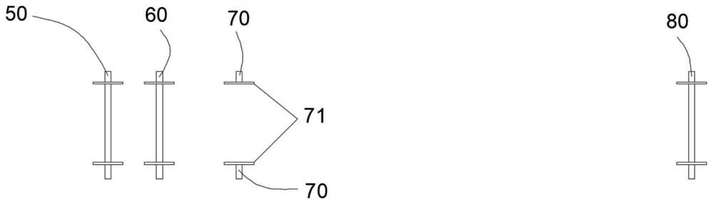
[0026] Such as Figure 1 to Figure 5 As shown, a slag removal machine includes a melting pot 10, a pot cover 20, an inlet 21, a fixed plate 30, a rotating plate 40, a motor fixing bracket 41, ...


PUM


Abstract

The invention relates to the technical field of molten metal surface slag salvaging, in particular to a slag salvaging machine which is provided with two rotatable chains, a plurality of shovel plates are uniformly fixed on the chains, the chains obliquely and downwards extend into a melting pot, a motor is arranged to drive the chains to rotate, the shovel plates on the chains sequentially sweep over molten lead and salvage dross of the molten lead in the melting pot, and the effect of automatic slag salvaging is achieved.

Description

technical field [0001] The invention relates to the technical field of slag removal on the metal liquid surface, in particular to a slag removal machine. Background technique [0002] The metal is smelted in the melting pot, and there will be some scum floating on the liquid after the metal is melted. [0003] In the prior art, in the prior art, the slag net is held by manual hands to carry out slag removal. Since the melting pot and the molten metal liquid surface in it are in a high temperature state, it has a bad influence on the physiology of the human body; secondly, Manual slag removal also makes human body fatigue. Contents of the invention [0004] In view of the above-mentioned deficiencies in the prior art, the present invention provides a slag removal machine, which realizes the technical effects of automatic slag removal and slag dumping. [0005] In order to achieve the above-mentioned purpose of the invention, the technical scheme adopted in the present inv...

Claims


Application Information

Patent Timeline
Patent Type & Authority Applications(China)
IPC IPC(8): F27D3/15
CPCF27D3/1563
Inventor 李想
Owner 李想
Why Eureka
Try Eureka