Line positioning structure based on low-voltage switchgear assembly

A switchgear and low-voltage complete set of technology, applied in the field of line positioning structure, can solve the problems that the equipment body cannot be flexibly adjusted according to needs, affect the normal use of low-voltage complete switchgear, and the electrical components of low-voltage complete switchgear are damaged, etc., to increase the scope of application, Prevent tearing off and improve safety

Inactive Publication Date: 2021-11-09
合肥巨步机械科技有限公司
View PDF1 Cites 0 Cited by
  • Summary
  • Abstract
  • Description
  • Claims
  • Application Information

AI Technical Summary

Problems solved by technology

[0005] The purpose of the present invention is to provide a line positioning structure based on low-voltage complete switchgear, through the cabinet structure, moving components, channel heat dissipation components, diversion fixed The design of the components solves the problem that the position of the equipment body inside the cabinet of the existing low-voltage switchgear is fixed, and the position of the equipment body cannot be flexibly adjusted according to the needs. When the low-voltage switchgear is subjected to a large impact, the wires between the equipment bodies It is easy to be torn off and fall off, which will cause damage to the electrical components in the low-voltage switchgear and affect the normal use of the low-voltage switchgear

Method used


Image

  • Line positioning structure based on low-voltage switchgear assembly
  • Line positioning structure based on low-voltage switchgear assembly
  • Line positioning structure based on low-voltage switchgear assembly

Examples


Embodiment Construction

[0048] The following will clearly and completely describe the technical solutions in the embodiments of the present invention with reference to the accompanying drawings in the embodiments of the present invention. Obviously, the described embodiments are only some, not all, embodiments of the present invention. Based on the embodiments of the present invention, all other embodiments obtained by persons of ordinary skill in the art without creative efforts fall within the protection scope of the present invention.

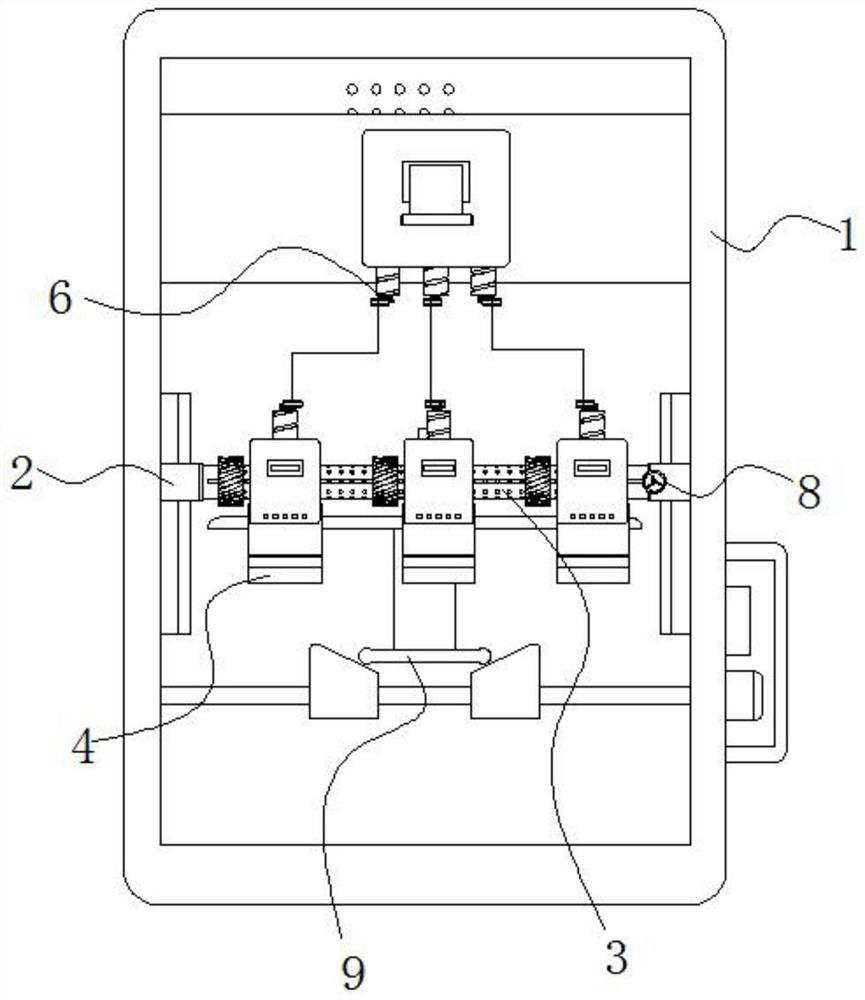
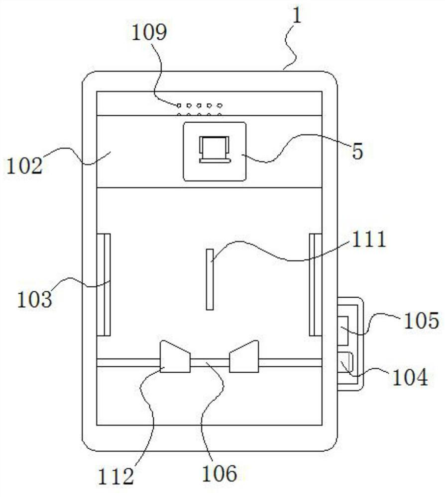
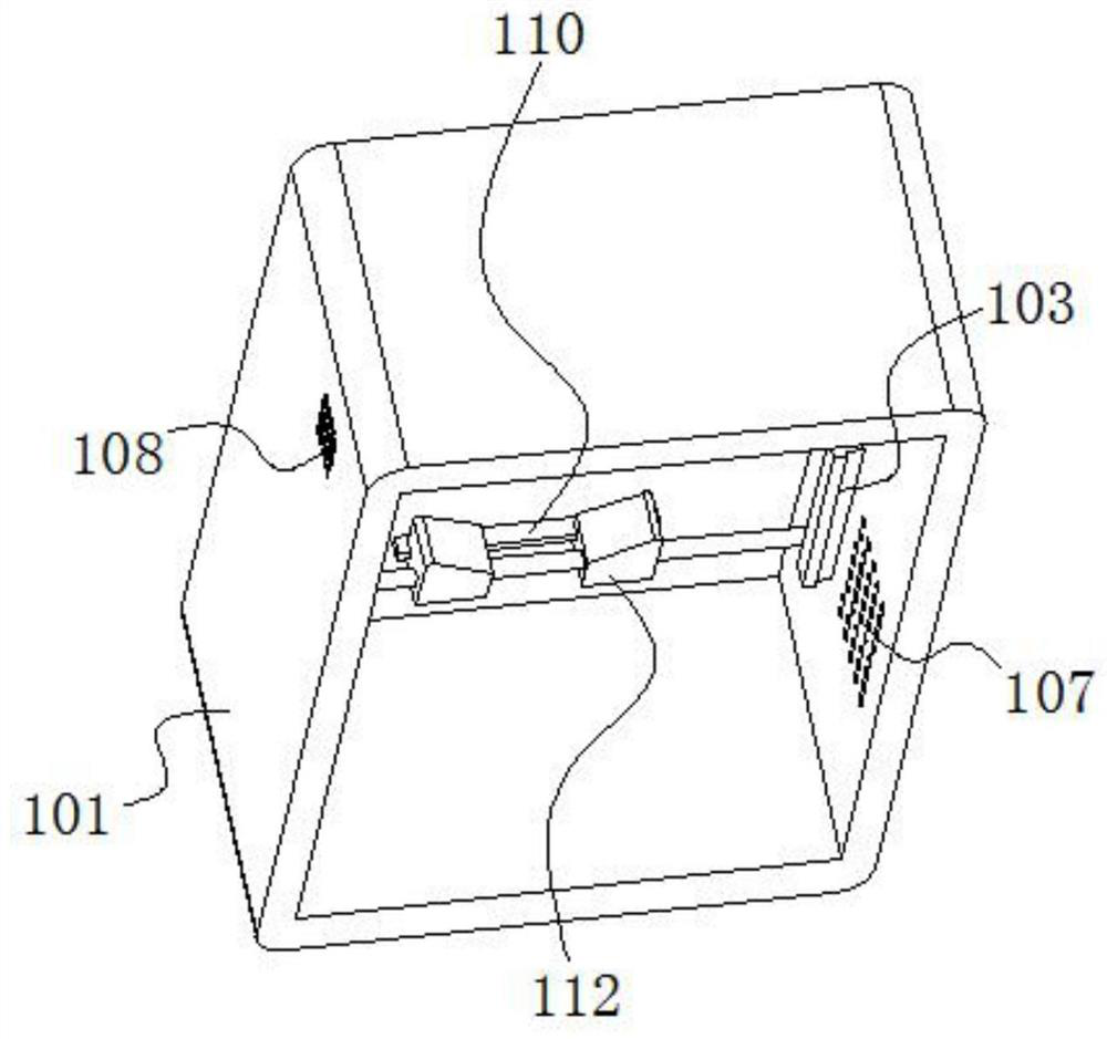
[0049] see Figure 1-13 , the present invention is a line positioning structure based on low-voltage complete switchgear, including a cabinet structure 1, the cabinet structure 1 includes a cabinet 101, and a mounting plate 102 is fixed on the inner wall of the cabinet 101 near the top; the cabinet 101 is opposite to the two First guide rails 103 are fixed on the inner surfaces;

[0050] The side of the first guide rail 103 is slidingly connected with the mobile a...


PUM


Abstract

The invention discloses a line positioning structure based on a low-voltage switchgear assembly, and relates to the technical field of switchgear equipment. The line positioning structure comprises a cabinet body structure, wherein a mounting plate is fixed on the inner wall of the cabinet body, first guide rails are fixed on two opposite inner side surfaces of the cabinet body, moving assemblies are slidably connected to the peripheral side surfaces of the first guide rails, a channel type heat dissipation assembly is connected between the two opposite moving assemblies, and is sleeved with a flow guide fixing assembly, equipment bodies are mounted on the surface of the flow guide fixing assembly and the surface of the mounting plate, and the top of the equipment body on the flow guide fixing assembly and the bottom of the equipment body on the mounting plate are fixedly provided with anti-falling positioning assemblies. Through the design of a hollow heat dissipation flow guide column, the flow guide fixing assembly, an internal threaded ring, a limiting sliding groove and a limiting block, the internal threaded ring is rotated, the horizontal position of the flow guide fixing assembly is flexibly adjusted through the thread matching effect of the internal threaded ring and the hollow heat dissipation flow guide column, and the position of the equipment body can be flexibly adjusted according to needs.

Description

technical field [0001] The invention belongs to the technical field of switchgear, and in particular relates to a line positioning structure based on a low-voltage complete set of switchgear. Background technique [0002] With the development of society and the continuous advancement of science and technology, a complete set of equipment refers to an industrial complex for the production of finished or semi-finished products. It can be a section, a production line, a workshop or a factory, it can be a single item of equipment for a certain profession, or it can be It is a comprehensive equipment of several professions. [0003] After retrieval, the application number is CN202022539603.2, an electrical low-voltage complete switchgear, which discloses that bolts are fixedly installed on both sides of the inner cavity of the cabinet body, vertical rails are fixed on both sides of the inner cavity of the cabinet body through bolts, and slide on the vertical rails. A slide block...

Claims


Application Information

Patent Timeline
IPC IPC(8): H02B1/32H02B1/052H02B1/20H02B1/54H02B1/56
CPCH02B1/32H02B1/052H02B1/202H02B1/54H02B1/565
Inventor 牛犇
Owner 合肥巨步机械科技有限公司
Why Eureka
Try Eureka