
Eureka
For R&D, Eureka makes reading and utilizing patents & technical documents easy.
Eureka AIR
Designed for self-driven R&D workflows. Generate viable solutions, solve complex R&D challenges, empower your innovation with AI.

Eureka Materials
Designed for material experts only. Revolutionize your material R&D, from search, analyze, to developing new materials.

TechResearch
Generate reliable direction feasibility study reports for your R&D in just a few steps.

TechSeek
Discover and master advanced knowledge NOW. Basics, ideas, possibilities, all at once.

TechMind
As an expert in R&D Theories, TechMind can generates customized viable solutions instantly.

TechRisk
Analyze your overall solution with one click, know your potential R&D risks in advance.

TechMonitor
Get weekly tech updates, stay abreast of the latest tech innovations and key insights.
Flow rate control device
A flow control device and flow technology, which is applied in the direction of flow control, measuring device, flow control of electric device, etc., can solve the problems of large flow measurement error and precision error, and achieve the effect of strong resistance to error
- Summary
- Abstract
- Description
- Claims
- Application Information
AI Technical Summary
Problems solved by technology
Method used
Image

Examples
Embodiment Construction
[0069] Hereinafter, embodiments of the present invention will be described with reference to the drawings, but the present invention is not limited to the following embodiments.
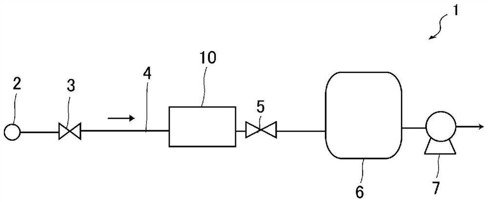
[0070] figure 1 A gas supply system 1 incorporating a pressure-type flow control device 10 according to an embodiment of the present invention is shown. The gas supply system 1 includes: a gas supply source 2; a flow control device 10, which is arranged in a flow path 4 forming a gas supply line; the downstream side; the processing chamber 6 connected to the downstream side of the on-off valve 5 ; and the vacuum pump 7 connected to the processing chamber 6 .
[0071] The flow control device 10 is provided to control the flow rate of the gas flowing in the flow path 4 . The vacuum pump 7 is capable of evacuating the processing chamber 6 and the flow path 4 , and supplies the flow-controlled gas to the processing chamber 6 while the downstream side of the flow control device 10 is depressurized. Var...
PUM
 Abstract
Description
Claims
Application Information
 - R&D Engineer
- R&D Manager
- IP Professional
- Industry Leading Data Capabilities
- Powerful AI technology
- Patent DNA Extraction
Browse by: Latest US Patents, China's latest patents, Technical Efficacy Thesaurus, Application Domain, Technology Topic, Popular Technical Reports.
© 2024 PatSnap. All rights reserved.Legal|Privacy policy|Modern Slavery Act Transparency Statement|Sitemap|About US| Contact US: help@patsnap.com