Vertical adjustable shoe brushing machine
A shoe brushing machine and type-adjusting technology, which is applied in the cleaning of boots and shoes, household cleaning devices, household appliances, etc., can solve the problems of mixing and affecting the cleaning effect of shoe uppers, etc.
- Summary
- Abstract
- Description
- Claims
- Application Information
AI Technical Summary
Problems solved by technology
Method used
Image
Examples
Embodiment 1
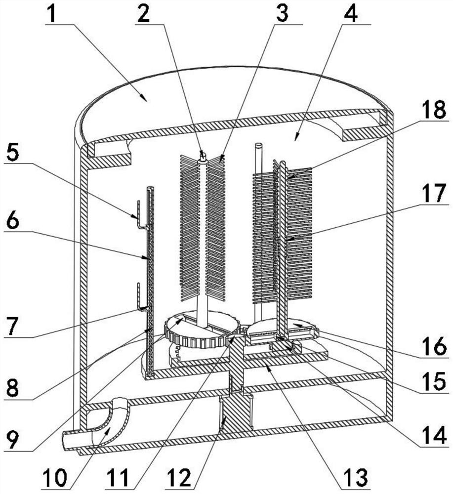
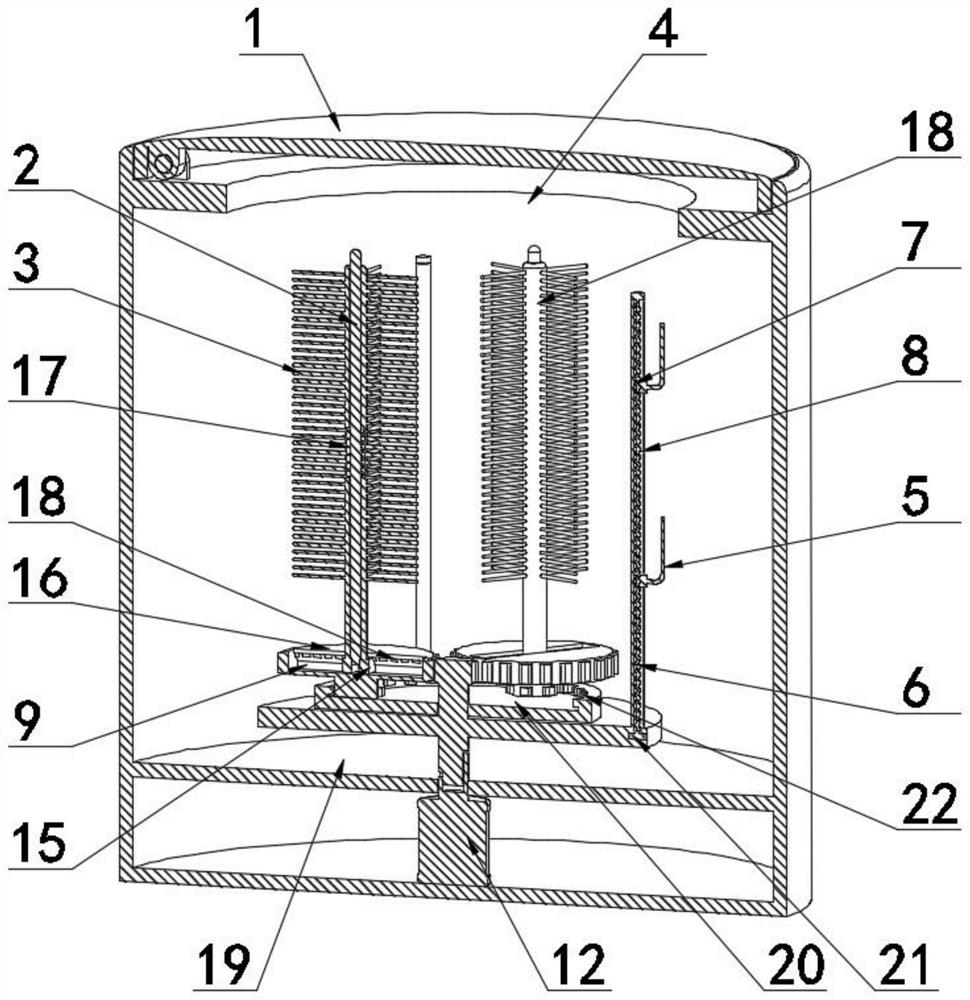
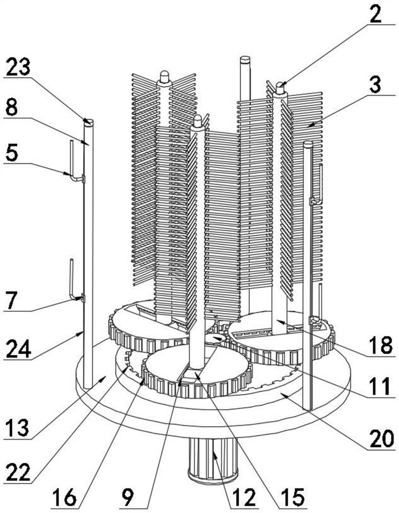
[0028] Embodiment one, with reference to Figure 1-6 , a vertical adjustable shoe brushing machine, comprising a bucket body 4 and a flip cover 1 that is rotatably connected to the top opening of the bucket body 4, a horizontally arranged partition 19 is fixed inside the bucket body 4, and a water outlet pipe is fixed on the partition 19 10. A drive motor 12 is fixed at the center of the bottom end of the barrel body 4, an outer brush 30 is fixed on the inner wall of the barrel body 4, a lower turntable 13 arranged horizontally is arranged inside the barrel body 4, and a plurality of rings and equidistant rings are fixed on the top of the lower turntable 13. The shoe-hanging mechanism is used to hang the shoes waiting to be scrubbed vertically, and a plurality of vertical brush mechanisms are arranged in a circular equidistant manner above the lower turntable 13, and is used to separate one side of the shoe upper to be scrubbed. For scrubbing, the first transmission gear 11 is...
Embodiment 2
[0029] Embodiment two, refer to Figure 1-6 The shoe-hanging mechanism includes a vertical bar 8 fixed at the top of the lower turntable 13 and a side slot 24 provided at one end of the vertical bar 8 away from the first transmission gear 11. The side slot 24 is slidably connected with the first slider 7, and the inner cavity of the vertical bar 8 is The screw rod 6 that is screwed and connected with the first slider 7 runs through, the second transmission gear 14 that is meshed with the inner gear ring 22 is fixed at the center of the bottom end of the third transmission gear 16, and the top end of the screw rod 6 is fixed with a rotary knob 23. 6. The bottom end is fixed with an inner swivel 21 that is rotatably connected to the inner cavity of the lower turntable 13. The end of the first slider 7 away from the first transmission gear 11 is fixed with a hanging rod 5. The hanging rod 5 is in an L-shaped structure. Side groove 24 is slidingly connected, and wherein, hanging b...
Embodiment 3
[0030]Embodiment three, refer to Figure 5 , the chute 9 is in a dovetail tenon-shaped structure, and there are multiple card slots 27, and the multiple card slots 27 are all arranged at the top positions on both sides of the chute 9, and the distance between adjacent two of the multiple card slots 27 is equal , wherein, the clamping blocks 26 can be alternately plugged into a plurality of clamping slots 27, so as to facilitate the adjustment and fixation of each position of the brush rod 18.
PUM
 Abstract
Description
Claims
Application Information
 - R&D
- Intellectual Property
- Life Sciences
- Materials
- Tech Scout
- Unparalleled Data Quality
- Higher Quality Content
- 60% Fewer Hallucinations
Browse by: Latest US Patents, China's latest patents, Technical Efficacy Thesaurus, Application Domain, Technology Topic, Popular Technical Reports.
© 2025 PatSnap. All rights reserved.Legal|Privacy policy|Modern Slavery Act Transparency Statement|Sitemap|About US| Contact US: help@patsnap.com


