Screwdriver

A screwdriver and helical wheel technology, applied to screwdrivers, manufacturing tools, etc., can solve problems such as low efficiency and inconvenient operation

Inactive Publication Date: 2021-11-12
李传聪
View PDF0 Cites 0 Cited by
  • Summary
  • Abstract
  • Description
  • Claims
  • Application Information

AI Technical Summary

Problems solved by technology

[0002] Before the screw is tightened or loosened, there is often a certain stroke. At this time, although the torque i

Method used


Image

  • Screwdriver
  • Screwdriver
  • Screwdriver

Examples


Embodiment Construction

[0030] The technical solutions in the embodiments of the present invention are clearly and completely described below in conjunction with the drawings in the embodiments of the present invention.

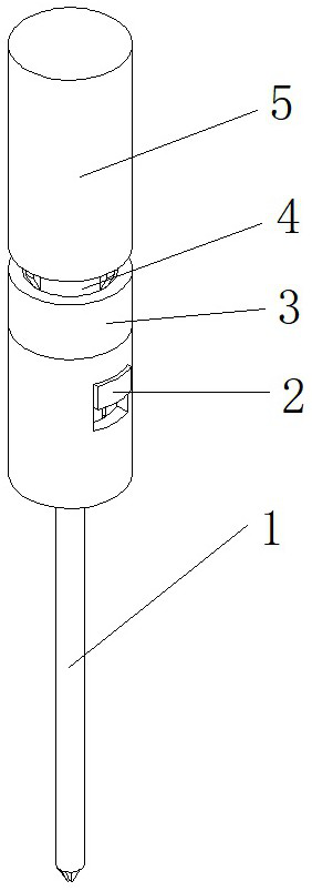
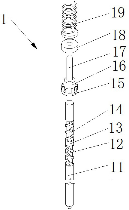
[0031] A screwdriver, comprising a shaft barrel 4, a wheel train 2 installed in the shaft barrel 4, a shaft system 1 installed on the wheel train 2, a dial ring 3 set outside the shaft barrel 4, and a casing fixed outside the shaft barrel 4 5.

[0032] The shaft cylinder 4 includes a cylindrical cylinder body 41, a screw wheel mounting nail 42 installed on the cylinder body 41, a 7-shaped stop claw 43 fixedly installed on the lower end of the cylinder body 41, and fixedly arranged in the cylinder body 41. The retarder cylinder 44.

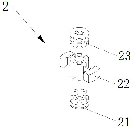
[0033] The gear train 2 includes a lower helical wheel 21 and an upper helical wheel 23 mounted on the lower end and upper end of the shafting 1 respectively, and a clutch spline sleeve 22 fitted on the shafting;

[0034] The inner sides of the lower h...


PUM


Abstract

A screwdriver comprises a shaft barrel, a gear train installed in the shaft barrel, a shaft system installed on the gear train, a shifting ring installed outside the shaft barrel in a sleeving mode and a shell fixed outside the shaft barrel. A screwdriver rod body is driven to rotate through pressing, the rotation direction of the screwdriver rod body is controlled through shifting of a clutch spline shaft, screwing or unscrewing of a screw is achieved, rotation or stopping of the screwdriver rod body is achieved through shifting of a shifting ring and controlling of separation and reunion of a stopping claw and a stopping wheel, and the problem that large torque is needed when the screw is loosened and fastened is solved through fixing of the screwdriver rod body.

Description

technical field [0001] The invention relates to the field of mechanical tools, in particular to a screwdriver. Background technique [0002] Before the screw is tightened or after it is loosened, there is often a certain stroke. At this time, although the torque is not large, the screwdriver needs to be continuously rotated, which is inefficient and inconvenient to operate. Contents of the invention [0003] In order to solve the above problems, the object of the present invention is to provide a screwdriver, which includes a shaft cylinder, a gear train installed in the shaft cylinder, a shaft system installed on the gear train, a dial ring sleeved outside the shaft cylinder, and a shaft fixed on the shaft. outer casing; [0004] By pressing, the shaft of the screwdriver is driven to rotate, by turning the clutch spline sleeve, the direction of rotation of the shaft of the screwdriver is controlled, and the screw is turned up or down, and by turning the ring, the clutch ...

Claims


Application Information

Patent Timeline
IPC IPC(8): B25B15/06
CPCB25B15/06
Inventor 李传聪
Owner 李传聪
Why Eureka
Try Eureka