System and method for detecting bag stacking state of bagged material loading machine

A technology of state detection and loading machine, which is applied in the direction of radio wave measurement system, conveyor, measuring device, etc., can solve the problem of code packet state without detection system, etc., and achieve good code packet effect, high economic benefit, and high precision Effect

Active Publication Date: 2021-11-12
HANGZHOU DIANZI UNIV
View PDF24 Cites 0 Cited by
  • Summary
  • Abstract
  • Description
  • Claims
  • Application Information

AI Technical Summary

Problems solved by technology

[0006] The purpose of the present invention is to address the defects of the prior art, and provide a system and method for detecting the state of the bagged material loading machine, using laser radar to solve the problem that the state of the bagged material loading machine does not have a detection system question

Method used


Image

  • System and method for detecting bag stacking state of bagged material loading machine
  • System and method for detecting bag stacking state of bagged material loading machine

Examples


Embodiment 1

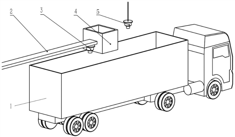
[0034] This embodiment provides a code package state detection system of a bagged material loading machine, such as figure 1 As shown, it includes a bagged material loading machine 1, an upper laser radar 5, a lower laser radar 3, and a controller. The upper laser radar 5 is arranged above the bucket of the bagged material loading machine, and the lower laser radar 3 is arranged The bottom of the stacking head 4 of the material loading machine does not affect the loading position; the controller is arranged inside the bagged material loading machine; the controller communicates with the upper laser radar 5 and the lower laser radar 3 respectively through data transmission lines. The controller of this embodiment can control the start and stop and data processing of the upper laser radar 5 and the lower laser radar 3; the main function of the upper laser radar 5 is to detect the size of the bagged material loading machine and the bagged material loading machine The edge part de...

Embodiment 2

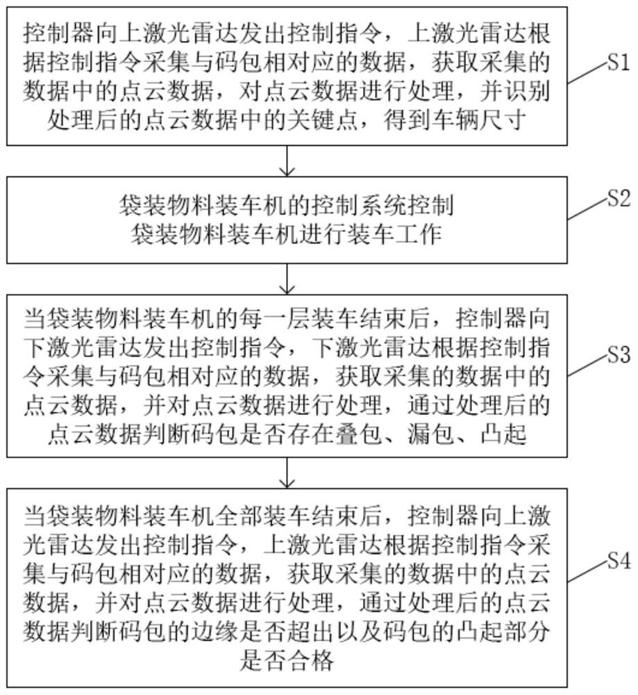
[0057] Correspondingly, there is also provided a method for detecting the status of coded bags of a bagged material loading machine, such as figure 2 shown, including:

[0058] S1. Determine whether the bagged material loader has entered the loading area. If so, the controller sends a control command to the upper laser radar, and the upper laser radar collects the data corresponding to the code package according to the control command, and obtains the point cloud data in the collected data. , process the point cloud data, and identify the key points in the processed point cloud data to obtain the vehicle size;

[0059] S2. The control system of the bagged material loading machine controls the bagged material loading machine to carry out the loading work;

[0060] S3. When the loading of each layer of the bagged material loading machine is completed, the controller sends a control command to the downward laser radar, and the downward laser radar collects the data correspondin...


PUM


Abstract

The invention discloses a system and method for detecting the bag stacking state of a bagged material loading machine. The related detecting system comprises the bagged material loading machine, an upper laser radar, a lower laser radar and a controller, and the controller is used for sending a control instruction to the upper laser radar or the lower laser radar. The lower laser radar is used for receiving the control instruction sent by the controller, collecting data corresponding to stacked bags according to the control instruction, acquiring point cloud data in the collected data, processing the point cloud data, and judging whether bag piling up, bag missing and bulging exist in the stacked bags or not according to the processed point cloud data. The upper laser radar is used for receiving the control instruction sent by the controller, collecting data corresponding to the stacked bags according to the control instruction, obtaining point cloud data in the collected data, processing the point cloud data, and judging whether edges of the stacked bags exceed the standard or not and whether the protruding parts of the stacked bags are qualified or not through the processed point cloud data.

Description

technical field [0001] The invention relates to the technical field of intelligent detection, in particular to a code bag state detection system and method of a bagged material loading machine. Background technique [0002] The bagged material loading machine is an automatic equipment for bagged material transportation, including conveyor belts, moving mechanisms, stacking heads, dust covers, positioning identification systems, control systems, etc. The conveyor belt is used for the transportation of bagged materials, the movement mechanism is used to realize the movement of the mechanism, the stacking head is used to put the bagged materials on the car, the positioning recognition system is used to identify the size and position of the car, and the control system is used to control Various actions after the movement of the whole mechanism. [0003] With the development of science and technology and the requirements of environmental protection, the use of bagged material lo...

Claims


Application Information

Patent Timeline
Patent Type & Authority Applications(China)
IPC IPC(8): B65G43/08B65G67/04G01B11/00G01S17/88
CPCB65G67/04B65G43/08G01S17/88G01B11/00B65G2203/04
Inventor 夏月冬胡小平万海波周霞王长昊
Owner HANGZHOU DIANZI UNIV
Why Eureka
Try Eureka