
Self-flowing energy dissipation concrete pouring method for deep foundation pit and concrete self-flowing energy dissipation structure

A concrete and deep foundation pit technology, which is applied in the direction of infrastructure engineering and construction, can solve the problems of excessive self-flowing speed of concrete, and achieve the effect of simple structure, guaranteed properties, and guaranteed construction quality

Active Publication Date: 2021-11-12
中铁十八局集团第五工程有限公司 +2
View PDF7 Cites 0 Cited by
  • Summary
  • Abstract
  • Description
  • Claims
  • Application Information

AI Technical Summary

Problems solved by technology

[0005] Aiming at the above-mentioned prior art, the present invention provides a pouring method suitable for self-flowing energy-dissipating concrete in deep foundation pits, which is mainly based on concrete self-flowing energy-dissipating structures and concrete drainage conduits to solve the problem of excessive concrete self-flowing speed when transporting concrete in deep foundation pits. Quick problem, reduce pouring impact force, ensure concrete properties

Method used


Image

  • Self-flowing energy dissipation concrete pouring method for deep foundation pit and concrete self-flowing energy dissipation structure
  • Self-flowing energy dissipation concrete pouring method for deep foundation pit and concrete self-flowing energy dissipation structure
  • Self-flowing energy dissipation concrete pouring method for deep foundation pit and concrete self-flowing energy dissipation structure

Examples


Embodiment Construction

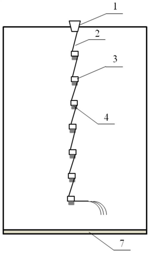
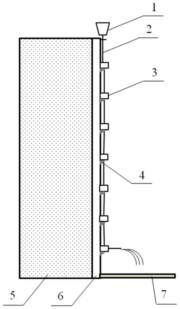
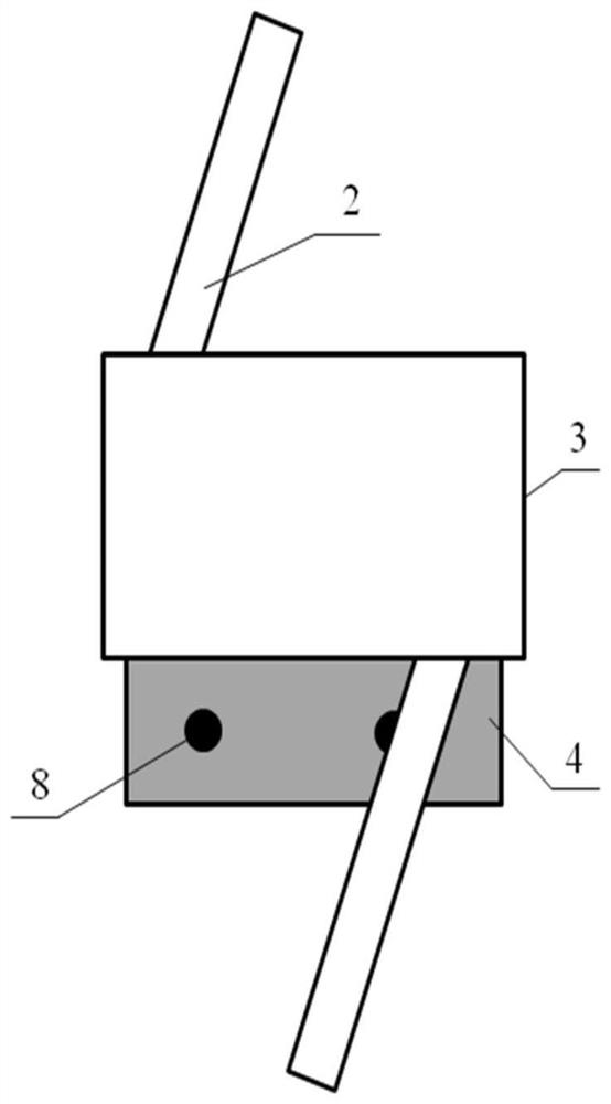
[0027] The design concept of a method for pouring self-flowing energy-dissipating concrete in deep foundation pits proposed by the present invention is: by adopting concrete self-flowing energy-dissipating structures to pour concrete in deep foundation pits, the concrete with higher kinetic energy flowing in from the upper drainage conduit passes through multi-stage energy-dissipating The buffer function of the box reduces the kinetic energy of the concrete, which is transported to the lower part through the drainage conduit at the lower part, and the energy is dissipated step by step. The energy dissipation box is connected with the lining wall through a triangular fixed structure, so as to ensure that the energy dissipation box can still be fixed in position when it bears a relatively large impact force. A drainage funnel is arranged at the entrance of the surface drainage conduit to facilitate the flow of concrete into the drainage conduit and transport to the deep undergrou...


PUM


Abstract

The invention discloses a self-flowing energy dissipation concrete pouring method for a deep foundation pit. Deep foundation pit concrete pouring is carried out through by adopting concrete self-flowing energy dissipation structure, before construction, arrangement, geometric dimensions, thicknesses and materials of energy dissipation boxes and drainage guide pipes are determined, the multi-stage energy dissipation boxes with upper holes and lower holes are sequentially arranged at intervals in the depth direction of the deep foundation pit from top to bottom, the multi-stage energy dissipation boxes are kept consistent in the vertical direction and connected with a lining wall of the foundation pit through fixing structures, the energy dissipation boxes are connected through the drainage guide pipes, after concrete is poured from the drainage guide pipes at the upper end, deep pouring is finally carried out through a discharging pipe at the lowermost end through the step-by-step energy dissipation buffering effect of the multi-stage energy dissipation boxes and transportation of the drainage guide pipe. Through the buffering effect of the energy dissipation boxes and transportation of the drainage guide pipes, the concrete can be stably transported from the earth surface to the deep foundation pit, good characters are kept, the flow speed is controlled to be small, impact of the concrete on bottom pouring of the deep foundation pit is reduced, and it is guaranteed that the characters of the concrete meet the construction requirement.

Description

technical field [0001] The invention relates to a foundation pit construction method, in particular to a deep foundation pit self-flow energy dissipation concrete pouring method. Background technique [0002] As my country's urbanization continues to accelerate, the size and population of cities have also increased rapidly, and urban land has become more and more tense. In order to alleviate the shortage of above-ground resources and traffic congestion in the city, buildings are gradually developed in the air and underground. Various buildings and structures such as high-rise or even super-high-rise buildings, underground parking lots, underground shopping malls, and underground stations have developed rapidly. In order to meet the construction requirements, it is usually necessary to increase the excavation depth of the foundation pit and expand the excavation scale of the foundation pit, and corresponding construction problems continue to emerge. [0003] In general foun...

Claims


Application Information

Patent Timeline
IPC IPC(8): E02D15/02E02D15/00
CPCE02D15/02E02D15/00E02D15/04
Inventor 李敏柴建国李文广樊秋林林集体李汉愿张树凯齐红海陈秀彬张营林浩高铎孙立强郎瑞卿王宇宇樊昭李天逢
Owner 中铁十八局集团第五工程有限公司
Learn More