Charging pile control method and device, equipment and storage medium

A control method and charging equipment technology, applied in charging stations, electric vehicle charging technology, electric vehicles, etc., can solve the problems of reducing the utilization rate of electric piles, operators cannot collect payments in time, and increase users' deduction of negative fees. Achieve flexible charging process, reduce the risk of collection and fund maintenance, and improve the utilization rate

Active Publication Date: 2021-11-16
SUNGROW POWER SUPPLY CO LTD
View PDF5 Cites 1 Cited by
  • Summary
  • Abstract
  • Description
  • Claims
  • Application Information

AI Technical Summary

Problems solved by technology

However, there are disadvantages in the billing method of the platform that calculates based on the amount of electricity and the rate. For example, the charging pile reports the charging amount every 15 to 60 seconds. , but the command to end charging has not been issued at this time. When the charging pile reports the power again for the n+1th time, the platform judges that the charging fee is higher than the user’s balance. At this time, the platform issues a command to end charging again, and the deduction will be negative. The value of the order makes the operator unable to collect the payment in time; and when the power of the charging pile is high, the charging efficiency will increase accordingly, and the charging power per unit time will also increase accordingly. During the time interval for reporting the charging quantity, due to the improvement of charging efficiency, the possibility of deducting the negative value fee will be increased, which may increase from a few cents to a few yuan. If the power station rate is high, the negative value fee will also increase. will increase accordingly; when the number of platform users reaches ten thousand levels, on the one hand, it will cause tens of thousands or even hundreds of thousands of losses to the power station, on the other hand, it will also increase the difficulty of collecting payments for the power station operators, and at the same time Reduce the utilization rate of electric piles

Method used


Image

  • Charging pile control method and device, equipment and storage medium
  • Charging pile control method and device, equipment and storage medium
  • Charging pile control method and device, equipment and storage medium

Examples


Embodiment 1

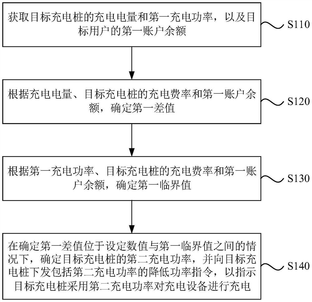
[0031] figure 1 It is a flow chart of a charging pile control method provided by Embodiment 1 of the present invention. This embodiment is applicable to the situation of controlling charging piles. The method can be executed by the charging pile control device, which can be controlled by software and / or hardware, and can be integrated into an electronic device that carries the control function of the charging pile, such as a server device.

[0032] Such as figure 1 As shown, the method may specifically include:

[0033] S110. Obtain the charging quantity and first charging power of the target charging pile, and the balance of the first account of the target user.

[0034] Wherein, the target charging pile refers to the charging pile that charges the charging equipment (such as a vehicle) belonging to the target user. The so-called charging power refers to the charging power reported by the target charging pile to the server from the beginning of charging the charging equipm...

Embodiment 2

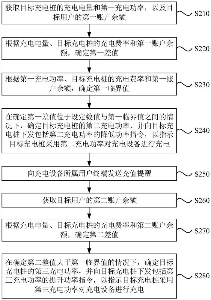
[0054] figure 2 It is a flow chart of a charging pile control method provided in Embodiment 2 of the present invention. On the basis of the above embodiments, it is further optimized to provide an optional implementation solution.

[0055] Such as figure 2 As shown, the method may specifically include:

[0056] S210. Obtain the charging quantity and first charging power of the target charging pile, and the balance of the first account of the target user.

[0057] S220. Determine a first difference according to the charging quantity, the charging rate of the target charging pile, and the first account balance.

[0058] S230. Determine a first critical value according to the first charging power, the charging rate of the target charging pile, and the first account balance.

[0059] S240. When it is determined that the first difference is between the set value and the first critical value, determine the second charging power of the target charging pile, and issue a power red...

Embodiment 3

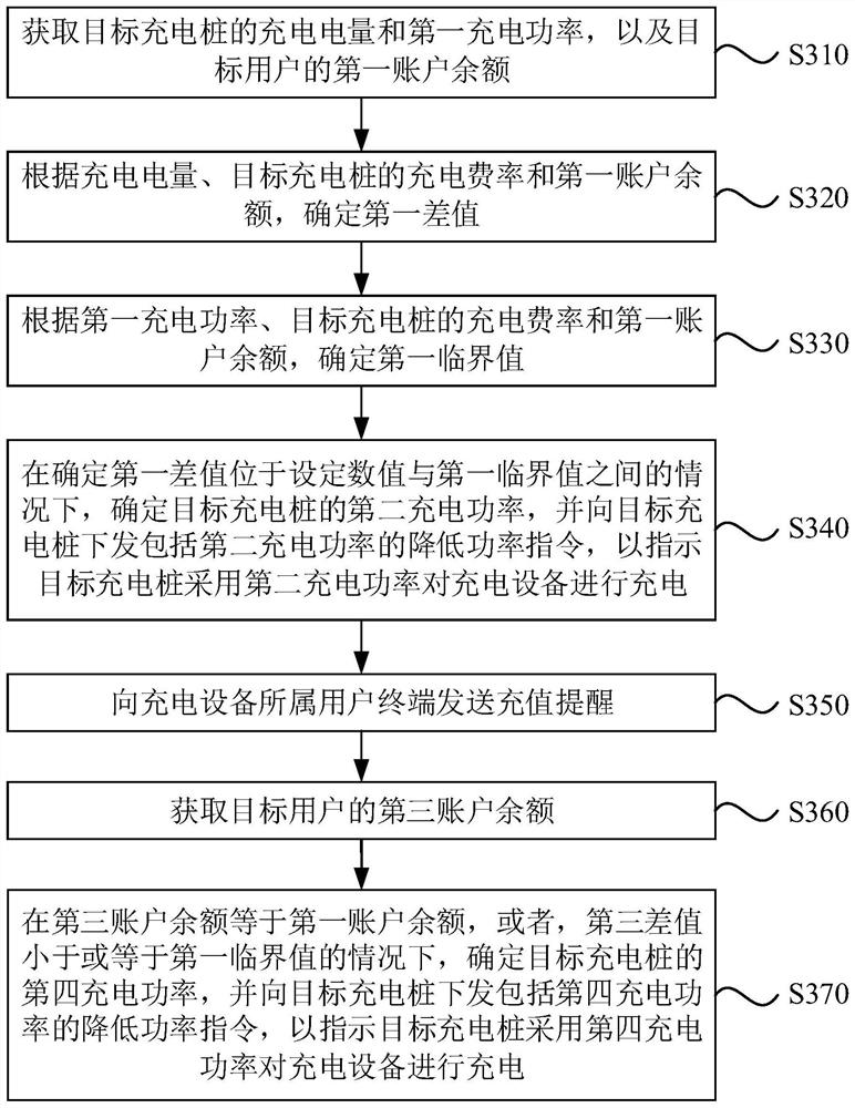
[0075] image 3 It is a flow chart of a charging pile control method provided in Embodiment 3 of the present invention. On the basis of the above embodiments, it is further optimized to provide an optional implementation solution.

[0076] Such as image 3 As shown, the method may specifically include:

[0077] S310. Obtain the charging quantity and first charging power of the target charging pile, and the balance of the first account of the target user.

[0078] S320. Determine a first difference according to the charging quantity, the charging rate of the target charging pile, and the first account balance.

[0079] S330. Determine a first critical value according to the first charging power, the charging rate of the target charging pile, and the first account balance.

[0080] S340. When it is determined that the first difference is between the set value and the first critical value, determine the second charging power of the target charging pile, and issue a power reduc...


PUM


Abstract

The invention discloses a charging pile control method and device, equipment and a storage medium, and belongs to the technical field of charging piles. The method comprises the steps of obtaining the charging electric quantity and first charging power of a target charging pile and the first account balance of a target user; determining a first difference value according to the charging electric quantity, the charging rate of a target charging pile and the first account balance; determining a first critical value according to the first charging power, the charging rate of a target charging pile and the first account balance; and under the condition that the first difference value is determined to be between a set value and the first critical value, determining second charging power of the target charging pile, and issuing a power reduction instruction including the second charging power to the target charging pile, so as to indicate the target charging pile to charge the charging device by adopting the second charging power. Through the technical scheme, the utilization rate of the charging pile is improved.

Description

technical field [0001] Embodiments of the present invention relate to the technical field of charging piles, and in particular, to a charging pile control method, device, equipment, and storage medium. Background technique [0002] With the rapid development of the new energy vehicle industry, the demand for vehicle charging piles has also increased, and as charging piles have been put into the market rapidly, the demand for the operation and management of charging piles has also increased. Therefore, charging pile operation management The platform came into being. For the charging operation platform, it is necessary to increase the utilization rate of charging piles and increase the accuracy of billing. [0003] At present, most charging pile platforms will issue a command to stop charging when the charging fee is greater than the user's balance, so as to prevent users from continuing to charge and occupy the charging pile after the user's balance is exhausted, thereby red...

Claims


Application Information

Patent Timeline
Patent Type & Authority Applications(China)
IPC IPC(8): B60L53/66B60L53/62
CPCB60L53/665B60L53/62Y02T10/70Y02T10/7072Y02T90/12Y02T90/16
Inventor 李雪王俊阳岳丰黄都伟王都好张贤磊张伟
Owner SUNGROW POWER SUPPLY CO LTD
Why Eureka
Try Eureka