Power distribution cabinet and use method thereof

A technology for power distribution cabinets and cabinets, which is applied to the substation/power distribution device shell, electrical components, substation/switch layout details, etc., which can solve the problems that the cooling liquid cannot be automatically replenished, affect the service life, and be scrapped, etc., to achieve Rapid and effective cooling effect, the effect of improving the service life

Inactive Publication Date: 2021-11-16
济南市中恒光机电技术中心
View PDF1 Cites 0 Cited by
  • Summary
  • Abstract
  • Description
  • Claims
  • Application Information

AI Technical Summary

Problems solved by technology

[0004] In order to solve the above technical problems, the present invention provides a power distribution cabinet and its use method to solve the problem that when the existing outdoor power distribution cabinet is in use, although the inside of the power distribution cabinet is equipped with a heat dissipation fan type heat dissipation structure, the power distribution cabinet cannot be used in hot summer weather. At the same time, if only the heat dissipation fan is used to dissipate the heat inside the power distribution cabinet, it is difficult to quickly dissipate the heat inside the power distribution cabinet. Although some outdoor power distribution cabinets are equipped with a water-cooled heat dissipation structure, the water-cooled heat dissipation structure The cooling liquid cannot be automatically replenished, so when a large amount of cooling liquid inside the water-cooled heat dissipation structure evaporates, the circulating water pump will pump air. The circulating water pump in the state of pumping air for a long time will not only affect the service life, And there will also be the problem of scrapping

Method used


Image

  • Power distribution cabinet and use method thereof
  • Power distribution cabinet and use method thereof
  • Power distribution cabinet and use method thereof

Examples


Embodiment

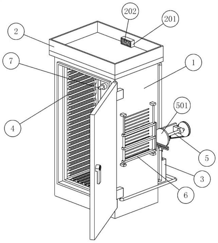
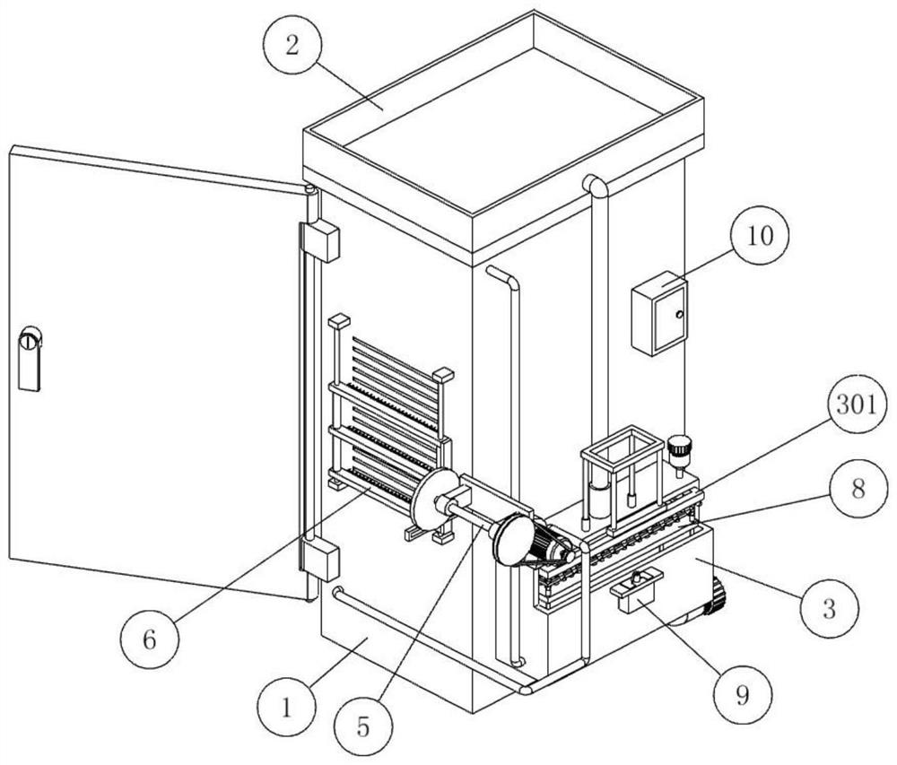
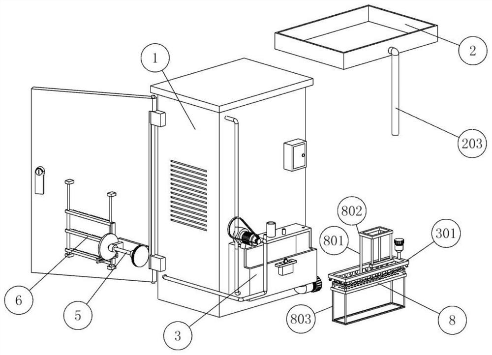
[0030] as attached figure 1 To attach Figure 11 Shown:

[0031]The invention provides a method for using a power distribution cabinet. The method for using a power distribution cabinet is realized by using a special power distribution cabinet, thereby improving the service life of the power distribution cabinet; the power distribution cabinet includes: a cabinet body 1; The top of the body 1 is provided with a rain collecting part 2, which is used to collect and utilize rainwater and reduce the cost of cooling liquid. 2. A frame-shaped version 201 is provided on the rear side of the interior outside the outlet hole, and a permeable geotextile 202 is provided on the front side of the frame-shaped version 201. The setting of the permeable geotextile 202 makes it difficult for other dust and other sundries inside the rain-collecting part 2 to Into the downpipe 203, thereby effectively avoiding the clogging phenomenon caused to the downpipe 203; The rear side of the rain part ...


PUM


Abstract

The invention provides a power distribution cabinet and a use method thereof. The use method of the power distribution cabinet is realized by using a special power distribution cabinet, thereby prolonging the service life of the power distribution cabinet. The power distribution cabinet comprises a cabinet body; the top of the cabinet body is provided with a rainwater collecting part, and the rear side of the rainwater collecting part is connected with a water storage tank installed on the lower portion of the rear end face of the cabinet body. A heat absorption part is arranged in the cabinet body; and the right rear part of the cabinet body is rotatably connected with a transmission member through a rotating support, and the right end surface of the cabinet body is provided with a cleaning part at a heat dissipation hole. Heat absorbed by the outer walls of four heat absorption pipes is brought into a second frame-shaped pipe through water in the water storage tank, then flows back into the water storage tank through a water return pipe, and is dissipated through the outer walls of the water storage tank, and the operation is repeated, so that the interior of the cabinet body can be rapidly and effectively cooled.

Description

technical field [0001] The invention belongs to the technical field of power distribution cabinets, and more specifically relates to a power distribution cabinet and its usage method. Background technique [0002] Power distribution cabinets are divided into power distribution cabinets, lighting distribution cabinets, and metering cabinets, and are the final equipment of the power distribution system. The power distribution cabinet is a general term for the motor control center. The power distribution cabinet can also be divided into indoor power distribution cabinet and outdoor power distribution cabinet. When the outdoor power distribution cabinet is in use, too high internal temperature will affect the service life of the electrical components inside the power distribution cabinet. For example, the application number: CN202010509009.0 The present invention belongs to the field of power distribution cabinets, and in particular relates to a self-moving anti-seepage outdoor...

Claims


Application Information

Patent Timeline
Patent Type & Authority Applications(China)
IPC IPC(8): H02B1/56H02B1/30
CPCH02B1/565H02B1/30
Inventor 马斌
Owner 济南市中恒光机电技术中心
Why Eureka
Try Eureka