Unlock instant, AI-driven research and patent intelligence for your innovation.

Valve assembly

A valve assembly and valve body technology, applied in the direction of brake assembly, pipe element, control valve, etc., can solve the problem that the effect of vibration suppression cannot be guaranteed, and achieve the effect of low manufacturing cost

Pending Publication Date: 2021-11-16
ROBERT BOSCH GMBH
View PDF7 Cites 0 Cited by
  • Summary
  • Abstract
  • Description
  • Claims
  • Application Information

AI Technical Summary

Problems solved by technology

[0007] Here, it is considered a disadvantage that the vibration damping effect cannot be guaranteed over the entire life of the vehicle

Method used


Image

  • Valve assembly
  • Valve assembly
  • Valve assembly

Examples


Embodiment Construction

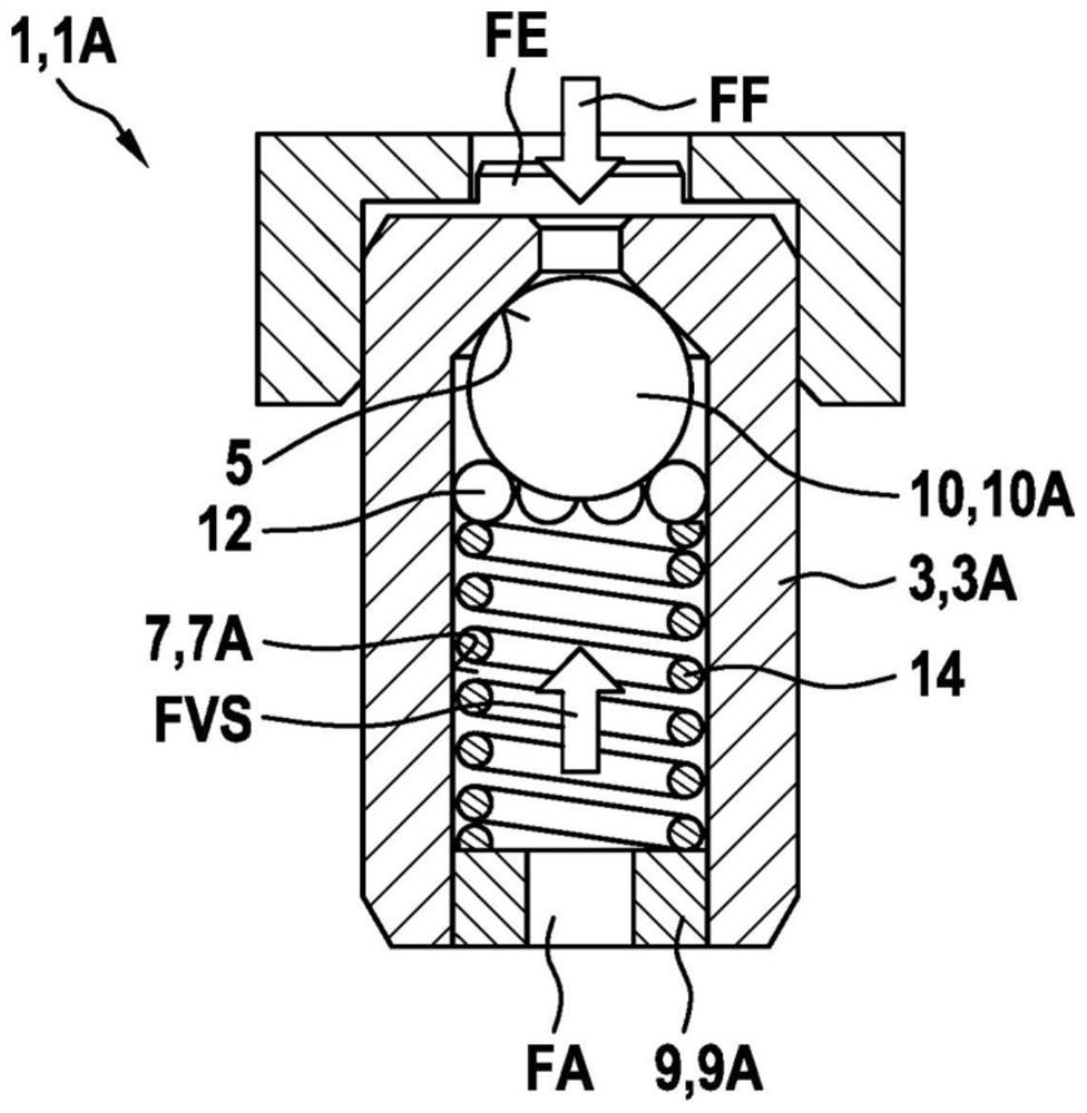
[0041] as from Figure 1 to Figure 9 It can be seen that the illustrated embodiments of the valve assembly 1 according to the invention each comprise a valve body 3 , 3A, 3B, 3C in which a fluid channel 7 is formed connecting the fluid inlet FE with the fluid outlet FA. The closing body 10 , which is movably mounted in the fluid channel 7 , is acted upon with a prestressing force FVS in the direction of the valve seat 5 formed in the valve body 3 , 3A, 3B, 3C, wherein the fluid force FF acts against the prestressing force FVS. Closing body 10 to open valve seat 5. In this case, the closing body 10 is guided axially and / or radially by at least one guide ball 12 . Furthermore, at least one guide ball 12 is arranged between the closing body 10 and the lateral boundaries of the fluid channel 7 .

[0042] as from Figure 1 to Figure 9 It can also be seen that the pretensioning force FVS acts on the closing body 10 at an angle via at least one guide ball 12 and that the at least ...


PUM


Abstract

The invention relates to a valve assembly (1), comprising a valve body (3) in which a fluid channel (7) is formed that connects a fluid inlet (FE) to a fluid outlet (FA), wherein a preload force (FVS) is applied to a closing body (10), which is movably mounted in the fluid channel (7), in the direction of a valve seat (5) formed in the valve body (3), a fluid force (FF) acting on the closing body (10) against the preload force (FVS) in order to open the valve seat (5). The closing body (10) is guided axially and / or radially by at least one guide ball (12), the guide ball (12) being arranged between the closing body (10) and a lateral boundary of the fluid channel (7).

Description

technical field [0001] The invention relates to a valve assembly of the type according to independent claim 1 . Background technique [0002] Known vehicle braking systems with ABS and / or ESP functions provide additional functions, for example to support the driver when maintaining a distance from a vehicle driving ahead. This is due to the fact that the additional function actively intervenes in the vehicle's braking system by building up pressure at the wheel brake calipers without the driver having to actuate the brake pedal himself. In order to prevent the driver from hearing disturbing noises, hydraulic damping measures are used which reduce pressure pulsations from the devices of the delivery unit of the vehicle brake system. Damping measures can consist of hydraulic resistance and capacity. For the effectiveness of such hydraulic shock absorbers, a large throttling through hydraulic resistance is used. Here, it can be regarded as a disadvantage that, with the high ...

Claims


Application Information

Patent Timeline
Patent Type & Authority Applications(China)
IPC IPC(8): B60T15/02F16K15/02F16K17/04F16K15/04
CPCF16K17/0433F16K17/105B60T15/02F16K15/044F16K15/046F16L55/033F16K15/026B60Y2400/81F16K17/0406Y10T137/7927F16K15/042
Inventor A·莱希勒W·斯塔尔P·舍林格J·克洛伊策C·艾泽勒A·加特M·比勒尔M·克罗斯F·朔恩
Owner ROBERT BOSCH GMBH