
Circular saw with grinding function

A circular saw and functional technology, applied in the field of circular saws with grinding function, can solve the problems of wasting time and energy

Inactive Publication Date: 2021-11-19
赵浩翔
View PDF0 Cites 1 Cited by
  • Summary
  • Abstract
  • Description
  • Claims
  • Application Information

AI Technical Summary

Problems solved by technology

[0002] Circular saw is a relatively common tool, which is often used to cut profiles or plates, and the corresponding circular saw can cut the corresponding profiles or plates because it is driven by a motor to achieve high-speed operation. Separate the profile or plate, and because the profile or plate itself has many materials, not every material will not damage the tooth shape of the circular saw, and when cutting some materials that are easy to cause circular saw tooth damage, the circular saw at this time The tooth shape damage is more obvious, and after the circular saw tooth is damaged, the general method used by personnel is to directly replace the corresponding circular saw to maintain its sharpness. Although there are some existing equipment that can grind the circular saw There are many ways to keep the tooth shape of the circular saw sharp, but the method used is often to use only a triangular file to grind each tooth shape, which wastes a lot of time and energy for personnel

Method used


Image

  • Circular saw with grinding function
  • Circular saw with grinding function
  • Circular saw with grinding function

Examples


Embodiment Construction

[0021] The following will clearly and completely describe the technical solutions in the embodiments of the present invention with reference to the accompanying drawings in the embodiments of the present invention. Obviously, the described embodiments are only some, not all, embodiments of the present invention. Based on the embodiments of the present invention, all other embodiments obtained by persons of ordinary skill in the art without making creative efforts belong to the protection scope of the present invention.

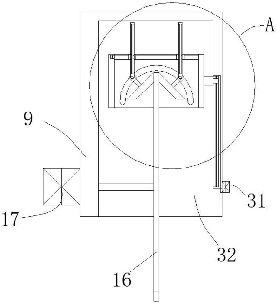
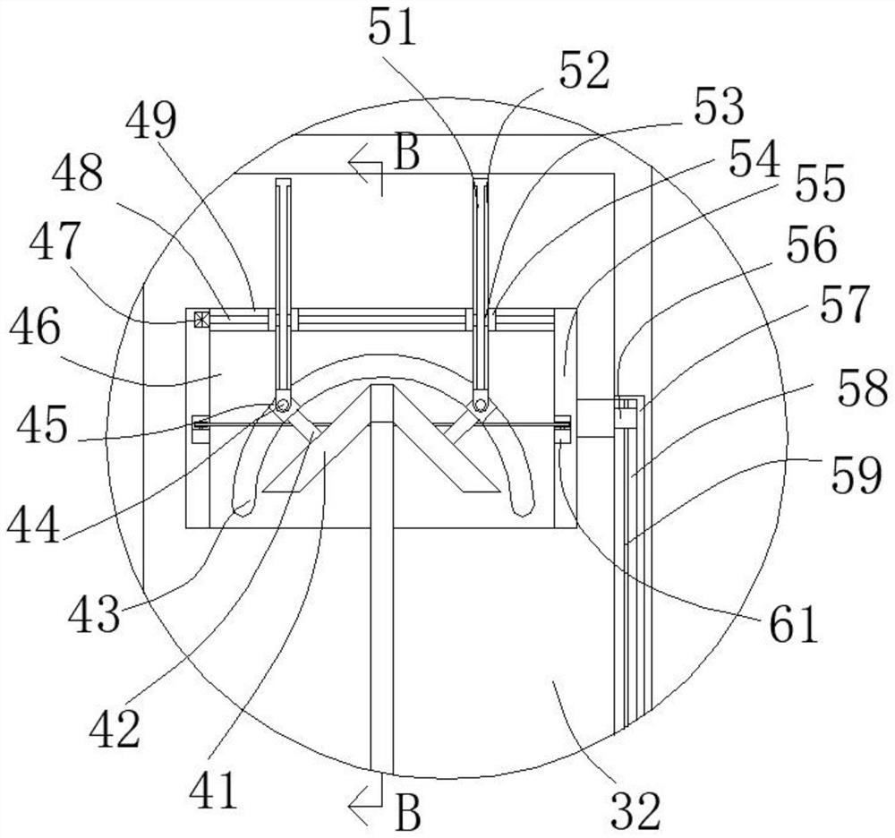
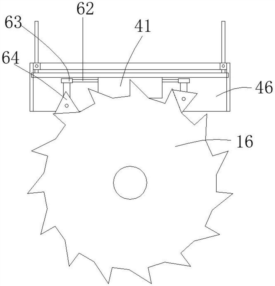
[0022] see Figure 1-7 , the present invention provides a technical solution: a circular saw with a grinding function, including an L-shaped connecting plate 9, the lower end of the L-shaped connecting plate 9 is connected with a cutting motor 17 by bolts, and the output shaft of the cutting motor 17 It runs through one side of the L-shaped connecting plate 9, and the output shaft end of the cutting motor 17 is provided with a cutting piece 16, and the L-shape...


PUM


Abstract

The invention discloses a circular saw with a grinding function. The circular saw with the grinding function comprises an L-shaped connecting plate, one side of the lower end of the L-shaped connecting plate is connected with a cutting motor through a bolt, an output shaft of the cutting motor penetrates through one side of the L-shaped connecting plate, a cutting blade is arranged at the end of the output shaft of the cutting motor, a matched inner cavity is formed in the L-shaped connecting plate, the cutting blade is located in the matched inner cavity, a middle box body is arranged in the matched inner cavity, an inner cavity is formed in the middle box body, symmetrical surrounding grooves are formed in the end walls of the two sides of the inner cavity in a communicating mode, symmetrical sliding blocks are arranged in the surrounding grooves in a sliding mode, matching column bodies are arranged between the positions, located on the two sides of the inner cavity, of the sliding blocks, connecting rods are arranged on one sides of the matching column bodies, and grinding cone pulleys are rotationally arranged on one sides of the connecting rods. According to the equipment, and a saw blade of the circular saw can be fully and efficiently ground through a triangular file so that the circular saw can be kept in a good working state.

Description

technical field [0001] The invention relates to the technical field of circular saw equipment, in particular to a circular saw with a grinding function. Background technique [0002] Circular saw is a relatively common tool, which is often used to cut profiles or plates, and the corresponding circular saw can cut the corresponding profiles or plates because it is driven by a motor to achieve high-speed operation. Separate the profile or plate, and because the profile or plate itself has many materials, not every material will not damage the tooth shape of the circular saw, and when cutting some materials that are easy to cause circular saw tooth damage, the circular saw at this time The tooth shape damage is more obvious, and after the circular saw tooth is damaged, the general method used by personnel is to directly replace the corresponding circular saw to maintain its sharpness. Although there are some existing equipment that can grind the circular saw There are many way...

Claims


Application Information

Patent Timeline
IPC IPC(8): B28D1/04B28D7/00B24B3/58B24B27/00B24B47/12B24B47/20B24B47/22B23D67/00
CPCB28D1/041B28D7/00B28D7/005B24B3/586B24B27/0076B24B47/22B24B47/12B24B47/20B23D67/00
Inventor 赵浩翔
Owner 赵浩翔
Learn More