Efficient air supply fan filter unit (FFU) with humidifying function

A functional and efficient technology, applied in the direction of air humidification system, heating and ventilation hood/cover, heating method, etc., can solve the problems of unable to meet the requirements of humidity and high dryness of fresh air, and achieve cost saving and high air delivery efficiency Effect

Pending Publication Date: 2021-11-19
深圳市佳莱环境股份有限公司
View PDF7 Cites 0 Cited by
  • Summary
  • Abstract
  • Description
  • Claims
  • Application Information

AI Technical Summary

Problems solved by technology

[0003] Chinese Patent Publication No. CN109340195B discloses a fan filter unit, including a unit box, an air inlet, an air outlet, a detachable mechanism and a fan, and a detachable mechanism is installed at the air outlet on the unit box. The detachable mechanism includes Detachable frame and fixing mechanism, micro-perforated plates are laid around the inner wall of the unit box, and the air inlet is connected with an air inlet pipe. The inside of the unit box is divided into the first chamber and the second chamber by the first partition and the second partition. room, the third chamber, the air inlet pipe passes through the first partition and connects with the second partition, the bottom of the unit box is the first filter layer, and the second filter layer is vertically arranged between the first filter layer and the second partition The filter layer and the third filter layer, the air outlet is set inside the detachable frame, and the unit box is equipped with a heat exchange device. Although it solves the problem of heating or cooling the fresh air to meet the different comfort requirements of users, it still exists The dryness of the fresh air is relatively high, which cannot meet the use of indoor areas that require humidity, and there are certain limitations in use

Method used


Image

  • Efficient air supply fan filter unit (FFU) with humidifying function
  • Efficient air supply fan filter unit (FFU) with humidifying function
  • Efficient air supply fan filter unit (FFU) with humidifying function

Examples


Embodiment Construction

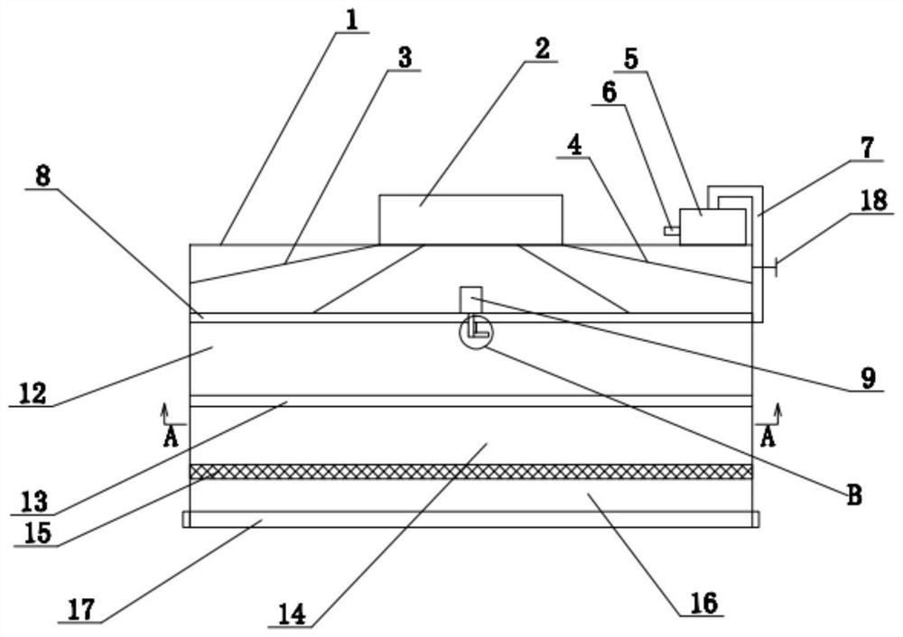
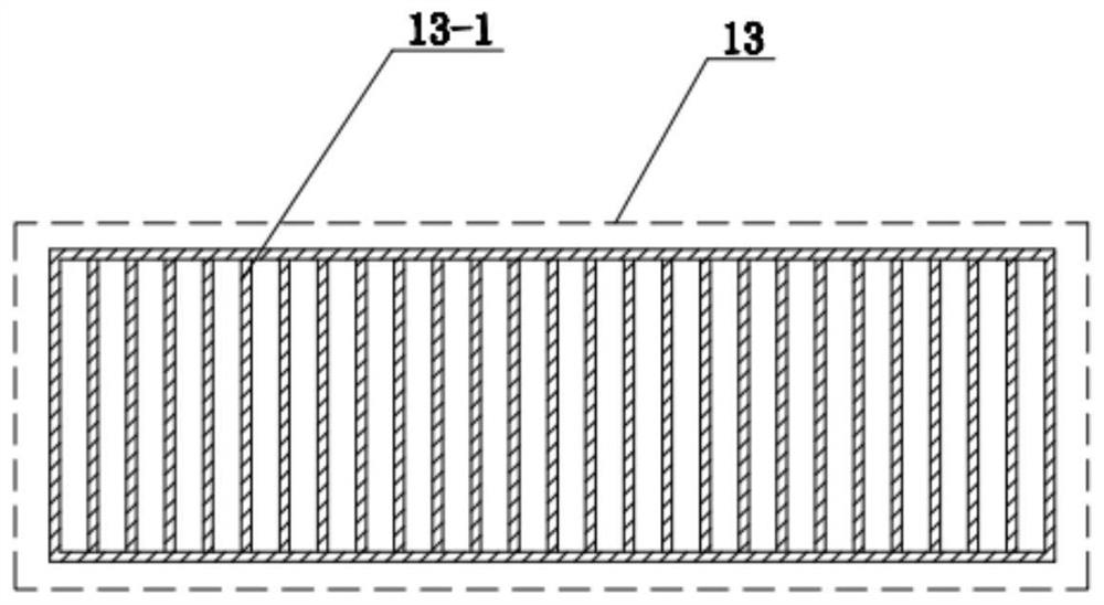
[0022] see Figure 1-Figure 3 As shown, the technical solution adopted in this specific embodiment is: it includes a frame body 1, a fan 2 is arranged on the frame body 1, the power of the fan 2 is 5.5Kw, and a first partition 8 is arranged in the frame body 1, and the first The dividing plate 8 is provided with a through hole, and the aperture of the through hole is 15mm, and the top of the first dividing plate 8 is provided with a first deflector 3 and a second deflector 4, and the second deflector 4 is connected with the first deflector. The inner side of the flow plate 3, the top plate openings of the first flow guide plate 3 and the second flow guide plate 4 communicate with the air outlet of the fan 2;

[0023] The right side of described blower fan 2 is provided with micro-water pump 5, and the power of micro-water pump 5 is 50W, and micro-water pump 5 is provided with water inlet 6, is connected with water pipe 7 on the water outlet end of micro-water pump 5, and a par...


PUM


Abstract

The invention discloses an efficient air supply fan filter unit (FFU) with a humidifying function, and relates to an air supply device. The efficient air supply FFU comprises a frame, wherein a fan is arranged on the frame, a first partition plate is arranged in the frame, two guide plates are arranged above the first partition plate, a miniature water pump is arranged on the right side of the fan, a water inlet is formed in the miniature water pump, a water pipe is connected to the water outlet end of the miniature water pump, a motor is arranged on the first partition plate, a nozzle is connected to a rotating shaft of the motor, a branch pipe is arranged on the nozzle, and the water pipe communicates with the nozzle through the branch pipe; and a second partition plate is arranged below the first partition plate, a first cavity is formed between the second partition plate and the first partition plate, a filter layer is arranged below the second partition plate, a second cavity is formed between the filter layer and the second partition plate, and an air outlet is formed below the filter layer. The situation that the indoor space is dry due to the air outlet mode of a traditional FFU is avoided, additional arrangement of a humidifier is reduced, and cost is saved.

Description

technical field [0001] The invention relates to the technical field of air filtering devices, in particular to an efficient air supply FFU with humidification function. Background technique [0002] Fan filter unit, the English full name is Fan Filter Unit, referred to as FFU. At present, FFU is widely used in clean rooms, clean benches, clean production lines, assembled clean rooms and local Class 100 applications. It can provide high-quality clean air for clean rooms and micro-environments of different sizes and cleanliness levels. FFU is equipped with primary and high-efficiency two-stage filters. The fan sucks the air from the top of the FFU and filters it through the primary and high-efficiency filters. The filtered clean air is sent out at a uniform speed of 0.45M / s±20% on the entire air outlet surface. Suitable for obtaining a high level of cleanliness in various environments. In the renovation of new clean rooms and clean workshops, the cleanliness level can be i...

Claims


Application Information

Patent Timeline
IPC IPC(8): F24F1/0073F24F1/0087F24F6/14F24F13/14F24F13/20F24F13/28
CPCF24F1/0087F24F1/0073F24F13/14F24F13/28F24F13/20F24F6/14
Inventor 马仁勤
Owner 深圳市佳莱环境股份有限公司
Why Eureka
Try Eureka