A near-eye virtual display device and a near-eye head-mounted virtual device

A virtual display and near-eye technology, applied in optical components, instruments, optics, etc., can solve problems such as strong rigid constraints, small eye movement range, difficulty in meeting the needs of different human head shapes, etc., and achieve the effect of efficient adjustment

Active Publication Date: 2022-01-28
SHENZHEN MVAIOT TECH CO LTD
View PDF7 Cites 0 Cited by
  • Summary
  • Abstract
  • Description
  • Claims
  • Application Information

AI Technical Summary

Problems solved by technology

Due to the differences in visual characteristics such as the pupillary distance and eye height of each person's eyes, the current AR virtual display components including prisms, free-form surfaces, optical waveguides and other technologies generally have FOV (Field of view, field of view), eye movement range, etc. Small and other problems, and most AR products have too strong rigid constraints on the spatial position of the display area (for example, glasses-type products also affect the original user's wearing of glasses), it is difficult to meet the different needs of different head shapes, and users cannot move well. The spatial position of the display area cannot meet the adjustment needs of users in different angles and directions
There is also a combination of connecting rods to realize the adjustment of the spatial position of the display of the head-mounted display. However, the products produced by this combination generally have problems such as large size, bulkiness, and complicated adjustment. Some technical solutions also have exposed connecting lines. In some The head is easily scratched when the equipment is dense or the working space is limited, which affects the safety of users

Method used


Image

  • A near-eye virtual display device and a near-eye head-mounted virtual device
  • A near-eye virtual display device and a near-eye head-mounted virtual device
  • A near-eye virtual display device and a near-eye head-mounted virtual device

Examples


Embodiment Construction

[0073] In order to make the purpose, technical solutions and advantages of the embodiments of the present disclosure clearer, the technical solutions in the embodiments of the present disclosure will be clearly and completely described below in conjunction with the drawings in the embodiments of the present disclosure. Obviously, the described embodiments It is a part of embodiments of the present disclosure, but not all embodiments. Based on the embodiments in the present disclosure, all other embodiments obtained by persons of ordinary skill in the art without making creative efforts belong to the protection scope of the present disclosure.

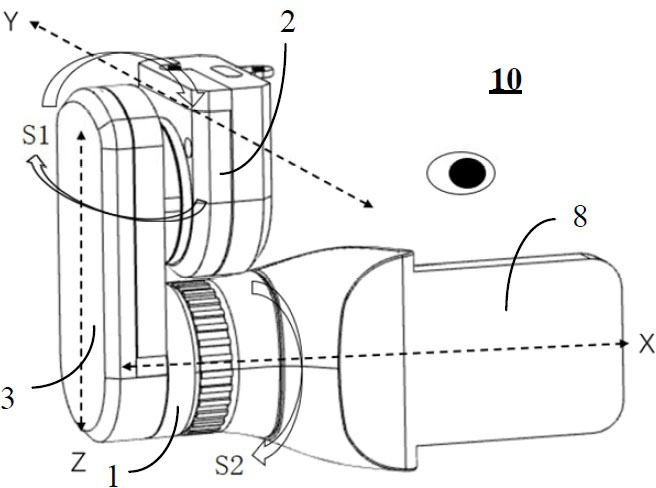
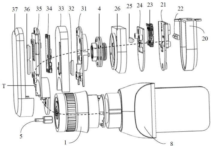
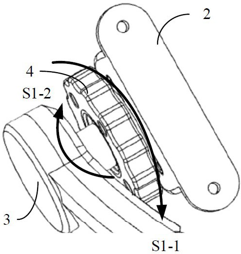
[0074] In one embodiment, such as figure 1 and figure 2 As shown, the embodiment of the present disclosure provides a near-eye virtual display device. The near-eye virtual display device 10 includes: a first translation adjustment component 1, a second translation adjustment component 2, a third translation adjustment component 3, and...


PUM


Abstract

The disclosure provides a near-eye virtual display device and a near-eye head-mounted virtual device, which belong to virtual display devices. The near-eye virtual display device includes: a second translation adjustment component, which is used to realize the front and rear translation of the virtual display component in the Y-axis direction; a first rotation adjustment component, which is respectively connected in rotation with the second translation adjustment component and the third translation adjustment component , to realize the storage and height adjustment of the virtual display components; the third translation adjustment component is used to realize the up and down translation of the virtual display components in the Z-axis direction; the second rotation adjustment component is connected with the third translation adjustment component and the first translation adjustment component respectively Assembling the combination to realize the angle adjustment of the display content of the virtual display component; the first translation adjustment component is movably connected with the virtual display component to realize the left and right translation of the virtual display component in the X-axis direction. In this way, the efficient adjustment of the spatial position of the near-eye head-mounted virtual display content is realized.

Description

technical field [0001] The present disclosure relates to the field of virtual display devices, in particular to a near-eye virtual display device and a near-eye head-mounted virtual device. Background technique [0002] Currently, monocular and binocular near-eye AR (Augmented Reality, augmented reality) head-mounted displays (Head-Mounted Display, HMD) are widely used in military, medical, industrial, security and entertainment scenarios. [0003] In order to form a virtual image at the intended location of the viewer, the optical device must meet various geometric and positional requirements. Such as the user's eye position, and the placement of the optical system relative to the user's eyes. Sometimes the user may want the virtual image content to be superimposed on the real world in the field of view, sometimes the virtual object is under the user's main viewing area as an auxiliary display, and sometimes the user also wants to store the display device temporarily so as...

Claims


Application Information

Patent Timeline
Patent Type & Authority Patents(China)
IPC IPC(8): G02B27/01
CPCG02B27/0176
Inventor 陆军林能清刘桂潮
Owner SHENZHEN MVAIOT TECH CO LTD
Why Eureka
Try Eureka