Manual energy storage device and circuit breaker

A technology of energy storage device and energy storage shaft, which is applied to the power device, circuit, electrical components and other directions inside the switch, can solve the problems of ratchet and thrust pawl damage, short mechanical service life, ratchet tooth wear, etc. , The overall structure is compact and stable

Pending Publication Date: 2021-11-19
ZHEJIANG HUAYI ELECTRIC APPLIANCE TECH
View PDF0 Cites 0 Cited by
  • Summary
  • Abstract
  • Description
  • Claims
  • Application Information

AI Technical Summary

Problems solved by technology

[0005] Therefore, the technical problem to be solved by the present invention is to overcome the relative displacement between the thrust pawl and the ratchet ratchet teeth in the prior art, which will easily cause the wear of the ratchet teeth, and long-term operation will cause damage to the ratchet wheel and thrust pawl, making the machine use The defect of short life; and the long-term thrust of the energy storage shaft, the contact surface is prone to wear, resulting in bouncing during operation, so the relative position between the energy storage shaft and the thrust pawl changes, resulting in the thrust pawl and the thrust pawl. Failure of ratchet fit

Method used


Image

  • Manual energy storage device and circuit breaker
  • Manual energy storage device and circuit breaker
  • Manual energy storage device and circuit breaker

Examples


Embodiment 1

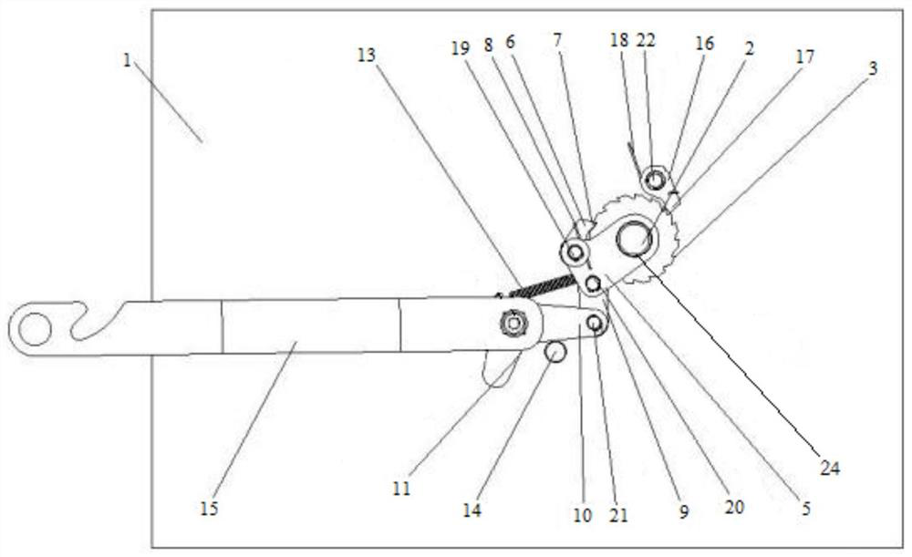
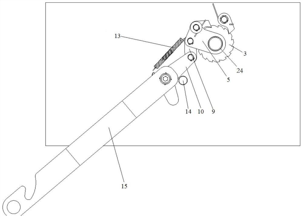
[0065] This embodiment provides a manual energy storage device, such as figure 1 , figure 2 , image 3 shown, including:

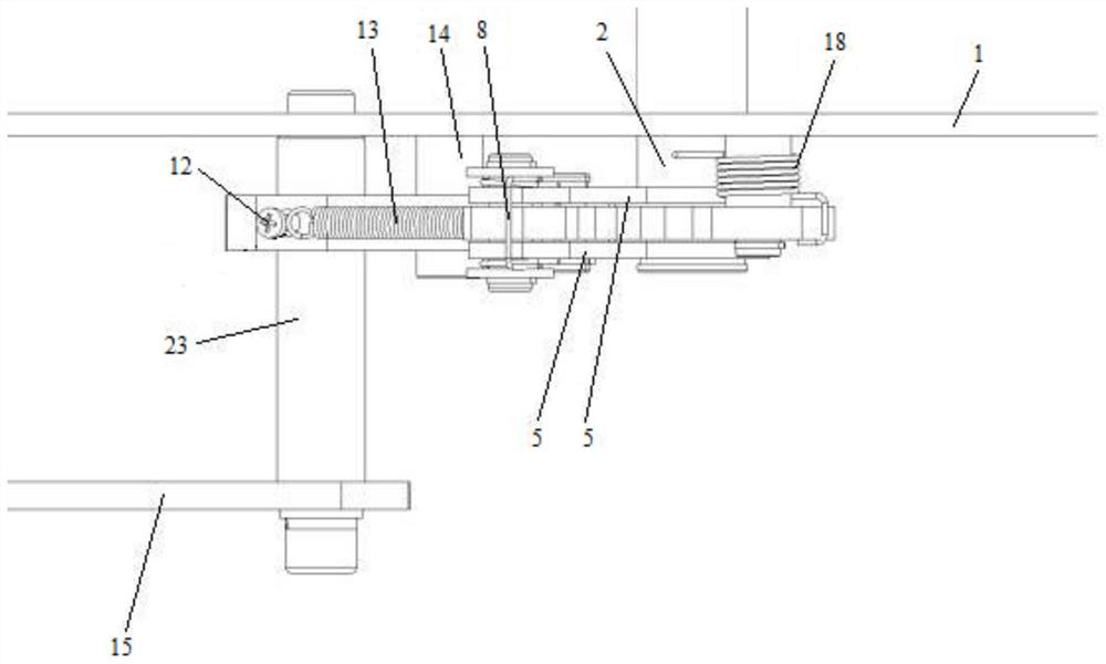
[0066] The installation plate 1 is provided with several installation holes for installing the subsequent energy storage shaft 2 , limit pin 14 , fourth pin 22 and fixed shaft 23 .

[0067] The energy storage shaft 2, the energy storage shaft 2 is rotatably mounted on the installation plate 1, the energy storage shaft 2 is connected to the intermediate transmission mechanism, and the rotation of the energy storage shaft 2 drives the intermediate transmission mechanism inside the circuit breaker , and finally realize the energy storage operation of the circuit breaker.

[0068] Ratchet 3, such as Figure 4 As shown, the ratchet 3 is disc-shaped, and ratchets are arranged on the circumference, and the ratchets cooperate with the subsequent thrust pawl 6 and limit pawl 16 to push the ratchet 3 to rotate and limit the ratchet 3 turn.

[0069] A through...

Embodiment 2

[0102] This embodiment provides a circuit breaker, including:

[0103] The base housing provides accommodating space and installation positions for the subsequent installation of the intermediate transmission mechanism, closing and opening mechanism, and manual energy storage device.

[0104] The intermediate transmission mechanism, the energy storage shaft 2 drives the intermediate transmission mechanism to make the energy storage spring act to realize the energy storage operation of the circuit breaker.


PUM


Abstract

The invention provides a manual energy storage device and a circuit breaker. The device comprises a mounting plate which is provided with a plurality of mounting hole positions; an energy storage shaft which is rotatably mounted on the mounting plate; a ratchet wheel which is connected to the energy storage shaft through a one-way bearing; two clamping plates which are arranged on the side, close to the mounting plate, of the ratchet wheel and the side, away from the mounting plate, of the ratchet wheel respectively, and are rotationally mounted on the energy storage shaft; a thrust pawl whihc is rotatably mounted between the two clamping plates through a first bolt; a limiting pawl which is rotatably arranged on the mounting plate through a fourth bolt; a connecting plate of which one end is rotatably connected to the clamping plates; a crank arm which is rotatably connected with the other end of the connecting plate; and a limiting pin which is arranged on the mounting plate. The technical problem to be solved by the invention is to overcome the defects of short service life and easy matching failure of a ratchet wheel and a thrust pawl caused by long-term operation.

Description

technical field [0001] The invention relates to the technical field of circuit breaker manual energy storage, in particular to a manual energy storage device and a circuit breaker. Background technique [0002] A circuit breaker is a mechanical switching device that can switch on and off the normal current of the carrying line, and can also switch on and off the carrying current under specified abnormal circuit conditions and within a certain period of time. When a serious overload, short circuit or undervoltage occurs on the line, it is necessary to immediately cut off the power supply to repair the equipment. At this time, the circuit breaker needs to store energy manually to provide energy for the closing operation. The energy storage of the circuit breaker is achieved by compressing the energy storage spring. The larger the energy storage spring, the greater the force required to compress it. It also means that the operator of the manual energy storage mechanism is used ...

Claims


Application Information

Patent Timeline
IPC IPC(8): H01H3/30
CPCH01H3/3005
Inventor 金旭赵运和连建勇曾繁国
Owner ZHEJIANG HUAYI ELECTRIC APPLIANCE TECH
Why Eureka
Try Eureka