Solder paste stirring device

A stirring device and solder paste technology, applied to mixers with rotating stirring devices, mixer accessories, transportation and packaging, etc., can solve problems such as difficult cleaning and easy adhesion of solder paste to the inner wall of the solder paste box

Inactive Publication Date: 2018-11-27
贵州锐旗威派通讯技术有限公司
View PDF4 Cites 4 Cited by
  • Summary
  • Abstract
  • Description
  • Claims
  • Application Information

AI Technical Summary

Problems solved by technology

[0004] The present invention intends to provide a solder paste stirring device to solve the problem that the solder paste is easy to adhere to the inner

Method used


Image

  • Solder paste stirring device
  • Solder paste stirring device

Examples


Embodiment Construction

[0018] Further detailed explanation through specific implementation mode below:

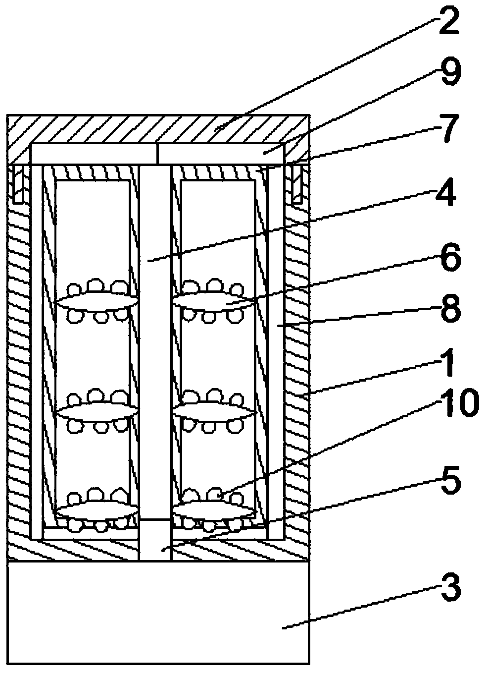
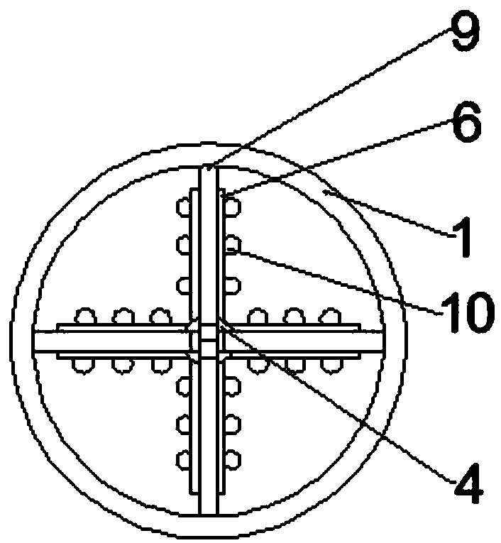
[0019] The reference signs in the accompanying drawings of the description include: mixing bucket 1, bucket cover 2, motor 3, stirring shaft 4, output shaft 5, stirring blade 6, rectangular frame 7, first scraper 8, second scraper 9, convex up to 10.

[0020] The embodiment is basically as attached figure 1 And attached figure 2 Shown: a solder paste stirring device, including a cylindrical structure of the mixing tank 1, the upper surface of the mixing tank 1 is provided with a cover 2, the outer bottom of the mixing tank 1 is provided with a motor 3, and the inside of the mixing tank 1 is vertically arranged There is a stirring shaft 4, the stirring shaft 4 is coaxial with the mixing barrel 1, the bottom end of the stirring shaft 4 is fixedly connected with the output shaft 5 of the motor 3, and several stirring groups are evenly distributed on the stirring shaft 4, and each stirring group i...


PUM


Abstract

The invention discloses a solder paste stirring device in the field of soldering material manufacturing equipment. A stirring shaft and a stirring drum are coaxial, the bottom end of the stirring shaft is fixedly connected with an output shaft of a motor, a plurality of stirring groups are uniformly and annularly arranged on the stirring shaft, each stirring group comprises a plurality of stirringblades, and the stirring blades and the stirring shaft are connected and collinear vertically. A rectangular frame is arranged between every two adjacent stirring groups, one side of each rectangularframe is fixedly connected with a stirring shaft while the other side of each rectangular frame is provided with a first scraper blade, and each first scraper blade fits the inner side wall of the stirring drum and is in rotational connection with the inner side wall of the stirring drum. The upper end face of each rectangular frame is provided with a second scraper blade, and each second scraperblade fits the lower surface of a cover and is in rotational connection with the lower surface of the cover. By adoption of the scheme, adhesion of solder paste on the inner side wall of the stirringdrum and the cover is effectively avoided in solder paste stirring, and accordingly convenience in cleaning is achieved.

Description

technical field [0001] The invention belongs to the field of solder material manufacturing equipment, and in particular relates to a solder paste stirring device. Background technique [0002] In the 1970s, Surface Mount Technology (SMT) refers to printing and coating solder paste on the pads of printed circuit boards, and accurately attaching surface mount components to the coated On the pad of solder paste, the circuit board is heated according to a specific reflow temperature curve to melt the solder paste, and its alloy components are cooled and solidified to form solder joints between components and printed circuit boards to achieve metallurgical connection. Solder paste is a new type of soldering material that accompanies SMT. Solder paste is a complex system, which is a paste mixed with solder powder, flux and other additives. Solder paste has a certain viscosity at room temperature, which can initially stick electronic components to a predetermined position. At the...

Claims


Application Information

Patent Timeline
IPC IPC(8): B01F7/18B01F7/32B01F15/00B01F27/96
CPCB01F27/074B01F27/091B01F27/092B01F27/808B01F27/96B01F27/90B01F35/123B01F35/3204
Inventor 谢继林张松明
Owner 贵州锐旗威派通讯技术有限公司
Why Eureka
Try Eureka