A device for assisting rehabilitation after arm fracture
A kind of equipment and arm technology, applied in the field of equipment for assisting rehabilitation after arm fractures, can solve problems such as troublesome operation and injuries, and achieve the effect of avoiding movement
- Summary
- Abstract
- Description
- Claims
- Application Information
AI Technical Summary
Problems solved by technology
Method used
Image
Examples
Embodiment 1
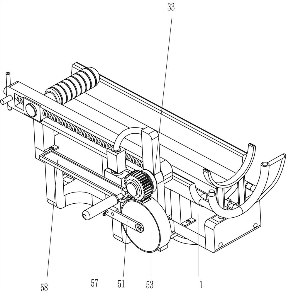
[0028] A device for assisting rehabilitation after arm fracture, such as Figure 1-Figure 5 As shown, it includes a base 1, a fixed frame 2, a bending mechanism 3 and a buffer mechanism 4. The rear of the base 1 is provided with a fixed frame 2, the fixed frame 2 is provided with a bending mechanism 3, and the fixed frame 2 is also provided with a buffer mechanism 4. .
[0029] The bending mechanism 3 includes a first fixing block 31, a first rotating shaft 32, a damping spring 33, a slotted sliding block 34, a screw 35, a torsion bar 36, a first sliding block 37 and a handle 38, and the left side of the inner bottom of the fixed frame 2 A first fixed block 31 is fixedly connected, the upper part of the first fixed block 31 is rotatably provided with a first rotating shaft 32, the rear part of the first rotating shaft 32 is wound with a damping spring 33, and the front part of the first rotating shaft 32 is circumferentially fixed with a slot. The sliding block 34, the middle...
Embodiment 2
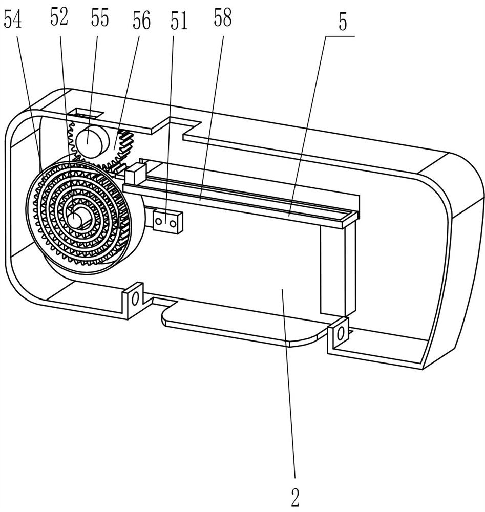
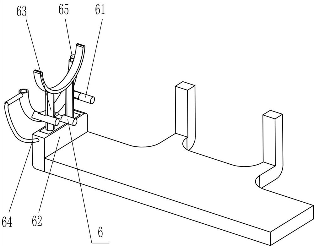
[0033] On the basis of Example 1, as figure 1 , image 3 , Image 6 and Figure 7 As shown, it also includes a speed-increasing mechanism 5, and the speed-increasing mechanism 5 includes a third fixed block 51, a second rotating shaft 52, a circular storage tray 53, a scroll rack 54, a third rotating shaft 55, a spur gear 56, The pull rod 57 and the guide groove plate 58 are provided with a third fixing block 51 on the left side of the inner bottom of the fixed frame 2. The left part of the third fixing block 51 is rotatably provided with a second rotating shaft 52. The storage tray 53, a scroll rack 54 is wound around the second rotating shaft 52, a third rotating shaft 55 is rotatably provided on the upper side of the left part of the fixed frame 2, and the front end of the third rotating shaft 55 is fixedly connected with the rear end of the first rotating shaft 32. A cylindrical gear 56 is fixed circumferentially in the middle of the three rotating shafts 55. The cylind...
Embodiment 3
[0038] On the basis of Example 1 and Example 2, as figure 1 and Figure 8 As shown, it also includes a fixed adsorption device 7, the fixed adsorption device 7 includes a fixed ring 71, a rubber pad 72 and a relief valve 73, the bottom of the base 1 is provided with three fixed rings 71 at intervals, and the fixed rings 71 are provided with rubber pads 72 , the rear of the fixing ring 71 is provided with a vent valve 73 .
[0039] Also includes a protective device 8, the protective device 8 includes a fourth fixed block 81, an arc plate 82 and an inflation hose 83, and a fourth fixed block 81 is spaced on the front side of the top of the base 1, and the top of the fourth fixed block 81 The arc-shaped plate 82 is fixedly connected, and the arc-shaped plate 82 is provided with an inflatable hose 83 at intervals, and the inflatable hose 83 is fixedly connected and communicated with the hollow fixing frame 61 .
[0040] When the device is moved to an appropriate position, the ru...
PUM
 Abstract
Description
Claims
Application Information
 - R&D
- Intellectual Property
- Life Sciences
- Materials
- Tech Scout
- Unparalleled Data Quality
- Higher Quality Content
- 60% Fewer Hallucinations
Browse by: Latest US Patents, China's latest patents, Technical Efficacy Thesaurus, Application Domain, Technology Topic, Popular Technical Reports.
© 2025 PatSnap. All rights reserved.Legal|Privacy policy|Modern Slavery Act Transparency Statement|Sitemap|About US| Contact US: help@patsnap.com


