
Solid-liquid separation and collection barrel for hematology department

A technology for solid-liquid separation and collection barrels, applied in the field of collection barrels, can solve problems such as plasma leakage, and achieve the effect of preventing blood clumping

Inactive Publication Date: 2021-11-23
王子胜
View PDF0 Cites 1 Cited by
  • Summary
  • Abstract
  • Description
  • Claims
  • Application Information

AI Technical Summary

Problems solved by technology

[0004] In order to overcome the shortcomings of the existing solid-liquid separation device, which easily leads to the leakage of plasma during the process of collecting plasma, the technical problem of the present invention is: to provide a hematology device that can realize separation and collection. Solid-liquid separation collection bucket

Method used


Image

  • Solid-liquid separation and collection barrel for hematology department
  • Solid-liquid separation and collection barrel for hematology department
  • Solid-liquid separation and collection barrel for hematology department

Examples


Embodiment 1

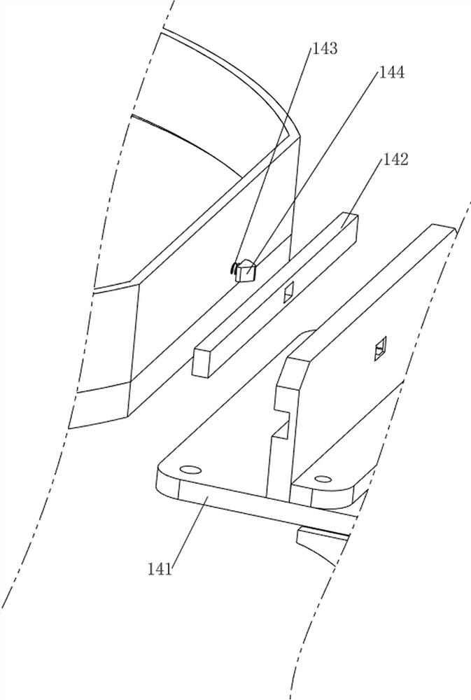
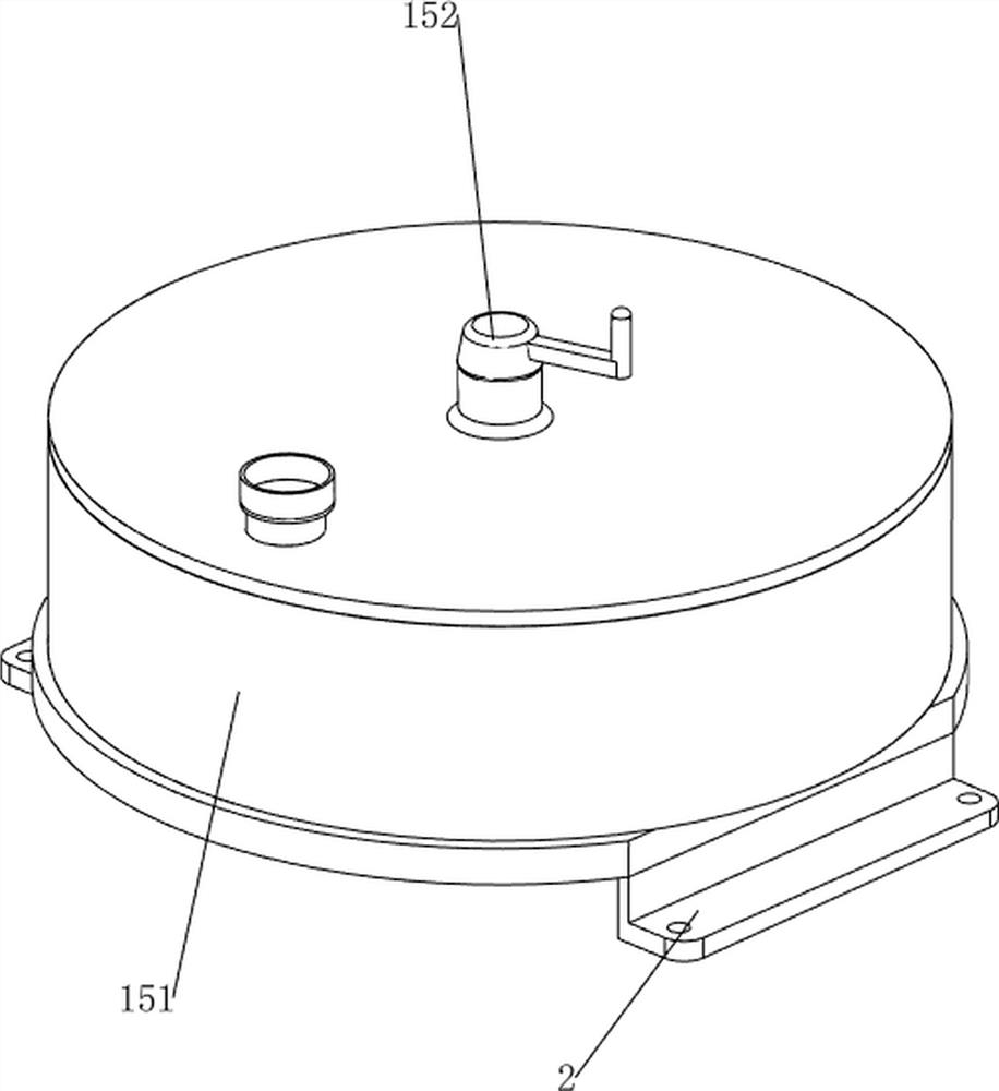
[0031] A hematology solid-liquid separation collection barrel, such as Figure 1-6 As shown, it includes a bottom plate 1, a support plate 2, a casing 3, a glass door 4, a cylinder 5, a first fixed block 6, a second fixed block 7, a pressure plate 8, a switch 9, a filter mechanism 10, a limit mechanism 11 and a reset Mechanism 12, the top of the bottom plate 1 is provided with a support plate 2, the top of the bottom plate 1 is provided with a casing 3, the front side of the casing 3 is rotatably connected with a glass door 4, the left and right sides of the casing 3 are connected with a cylinder 5, and the cylinder 5 on the right is a telescopic rod The first fixed block 6 is arranged on the top, and the second fixed block 7 is arranged on the telescopic rod of the cylinder 5 on the left side. There is a filter mechanism 10, a limit mechanism 11 is provided on the casing 3, and a reset mechanism 12 is arranged on the upper right part of the casing 3.

[0032] The filter mech...

Embodiment 2

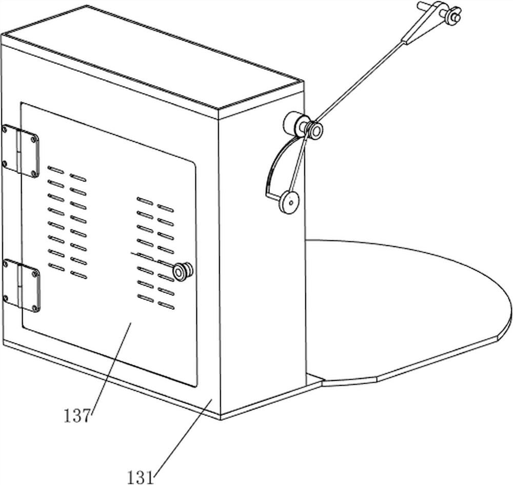
[0037] On the basis of Example 1, such as Figure 7-13 As shown, recovery mechanism 13 is also included, and recovery mechanism 13 includes collection box 131, second rotating block 132, opening and closing plate 133, the third torsion spring 134, roller 135, pull wire 136 and rotating door 137, and shell 3 rear side is provided with There is a collection box 131, the left side of the filter plate 101 is provided with a second rotating block 132, the upper part of the front side of the collection box 131 is rotatably connected with an opening and closing plate 133, and the left and right sides of the opening and closing plate 133 bottom and the collection box 131 are provided with a third rotating block. Torsion spring 134, the upper left side of the casing 3 is rotatably connected with a roller 135, a backguy 136 is connected between the left side of the opening and closing plate 133 and the second rotating block 132, the backguy 136 bypasses the roller 135, and the rear side ...


PUM


Abstract

The invention relates to a collecting barrel, in particular to a solid-liquid separation and collection barrel for the hematology department. The technical problem of the invention is to provide a solid-liquid separation and collection barrel for the hematology department, which is convenient for separation and collection. According to the technical scheme, the solid-liquid separation and collection barrel for the hematology department comprises a bottom plate, a supporting plate, a shell, a glass door, air cylinders, a first fixing block, a second fixing block, a pressing plate and a switch, wherein the supporting plate is arranged at the top of the bottom plate, the shell is arranged at the top of the bottom plate, one side of the shell is rotationally connected with the glass door, the two sides of the shell are connected with the air cylinders, the first fixing block is arranged on the telescopic rod of the air cylinder on one side, the second fixing block is arranged on the telescopic rod of the air cylinder on the other side, the pressing plate is connected between the tops of the telescopic rods of the air cylinders, and the switch is arranged in the middle of the top of the pressing plate. Through cooperation of a filtering mechanism, a limiting mechanism and a resetting mechanism, a blood bag can be automatically extruded, solid-liquid separation is conducted on the blood bag, and people can conveniently take out solids.

Description

technical field [0001] The invention relates to a collection barrel, in particular to a hematology solid-liquid separation collection barrel. Background technique [0002] Blood is packed in blood bags. In medical research, pathological analysis and other research, blood and blood bags are usually separated, and then the blood is used. When solid-liquid separation is performed, blood is easily splashed and it is difficult to take out the blood bag. [0003] However, the existing solid-liquid separation device easily leads to plasma leakage during the process of collecting plasma during solid-liquid separation. Therefore, a hematology solid-liquid separation collection bucket that can facilitate separation and collection is now developed. Contents of the invention [0004] In order to overcome the shortcoming of the existing solid-liquid separation device that easily causes plasma leakage during the process of collecting plasma during solid-liquid separation, the technical...

Claims


Application Information

Patent Timeline
Patent Type & Authority Applications(China)
IPC IPC(8): B01D29/03B01D29/86B01D29/96B01F7/18
CPCB01D29/03B01D29/86B01D29/96
Inventor 王子胜
Owner 王子胜
Learn More