Rail electricity taking vehicle

A track and trolley technology, applied to circuits, electrical components, conveyors, etc., can solve problems such as inflexible use, low production efficiency, and heavy concrete products, and achieve the effect of simple overall structure, flexible use, and smooth running

Active Publication Date: 2021-11-23
FUJIAN QUNFENG MACHINERY
View PDF5 Cites 0 Cited by
  • Summary
  • Abstract
  • Description
  • Claims
  • Application Information

AI Technical Summary

Problems solved by technology

[0002]In the production of building materials, concrete products need to be cured in a curing kiln. The curing kiln can provide a certain temperature, humidity and pressure for concrete products, so that the concrete products can The structure is stronger; in the past, the concrete products were placed on the trolley, and the workers manually pushed them into the curing kiln for curing; but the concrete products were very heavy, which required a lot of manpower and time, and the production efficiency was low; then a rail car was developed. There is a track in the curing kiln, and the rail car walks on the rail to transport concrete products. The transportation speed is fast, and it saves a lot of manpower and time, and improves the production efficiency; but the driving wheels of this rail car need to be installed with driving motors to drive the track. When the car is running on the track, the driving motor needs to be connected to the power supply, usually using wires to connect to the mains; when the rail car is running, it will pull the wires to move accordingly. When the walking distance is long, the length of the wires needs to be very long, that is, the length of the wires must be If it is greater than the traveling distance of the rail car, otherwise the rail car will be restricted by the wires and cannot walk; when the traveling distance is short, the overly long wires will pile up and become disorganized; It is inconvenient to take care of and affects the normal running of the rail car; and the connection of wires makes the overall structure of the rail car complicated and inflexible to use

Method used


Image

  • Rail electricity taking vehicle
  • Rail electricity taking vehicle
  • Rail electricity taking vehicle

Examples


Embodiment Construction

[0047] In order to further explain the technical solution of the present invention, the present invention will be described in detail below through specific examples.

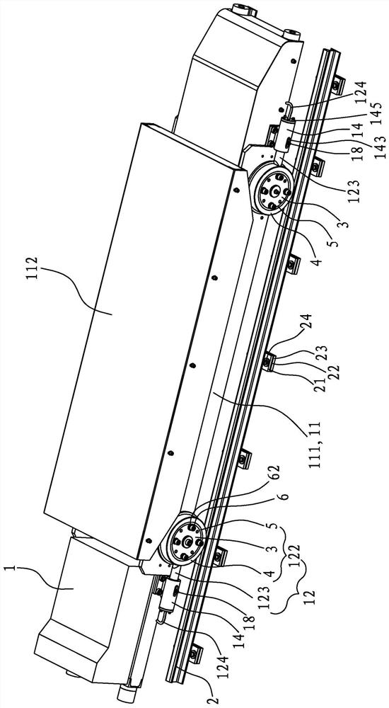
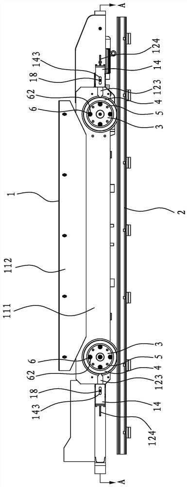
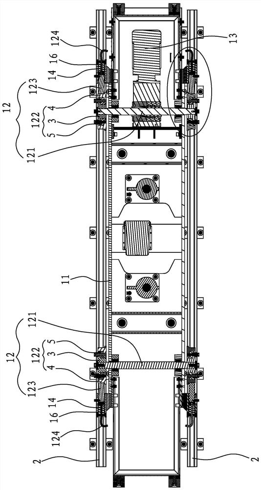
[0048] see Figure 1 to Figure 5 , the present invention discloses a rail-taking trolley, the rail-taking tram 1 walks on two rails 2, wherein one rail 2 is connected to a positive voltage, and the other rail 2 is connected to a negative voltage; the rail-taking tram 1 includes a frame 11. Two sets of walking wheel sets 12 arranged at both ends of the bottom of the vehicle frame 11 and a drive motor 13 for driving at least one set of walking wheel sets 12; each set of walking wheel sets 12 has a main shaft pivotally connected to the vehicle frame 11 121. Two walking wheels 122 located at both ends of the main shaft 121 and two electric pick-up rods 123 respectively abutting against the two walking wheels 122, the walking wheels 122 have inner rollers 3, outer rollers 4 and isolate inner rollers 3 and outer roll...


PUM


Abstract

The invention discloses a rail electricity taking vehicle. The rail electricity taking vehicle walks on two rails, wherein one rail is connected with positive voltage, and the other rail is connected with negative voltage; the rail electricity taking vehicle comprises a frame, two walking wheel sets and a driving motor; each walking wheel set is provided with a main shaft, two walking wheels and two electricity taking rods abutting against the two walking wheels separately; each walking wheel is provided with an inner-layer roller, an outer-layer roller and an insulating sleeve isolating the inner-layer roller and the outer-layer roller, the inner-layer roller is locked and fixed to the end of the main shaft, the outer ring of the inner-layer roller is sleeved with the insulating sleeve, the outer ring of the insulating sleeve is sleeved with the outer-layer roller, and the outer-layer roller walks on the rails; and one end of each electricity taking rod abuts against one outer-layer roller to take electricity, and the other end of each electricity taking rod is connected to the driving motor through an electric wire. The rail electricity taking vehicle is connected with a power supply, and the rail electricity taking vehicle takes electricity from the rails, so that the situation that normal walking of the rail electricity taking vehicle is affected due to complex wires when the wires are used for electrification can be avoided, and the rail electricity taking vehicle is simpler in overall structure and more flexible to use.

Description

technical field [0001] The invention relates to a rail-taking electric car. Background technique [0002] In the production of building materials, concrete products need to be cured in a curing kiln. The curing kiln can provide a certain temperature, humidity and pressure for the concrete products, so that the structure of the concrete products is stronger after forming; in the past, the concrete products were placed on the trolley, and the workers Manually push it into the curing kiln for curing; however, the concrete products are very heavy, requiring a lot of manpower and time, and the production efficiency is low; then a rail car was developed, and a track is set in the curing kiln, and the rail car walks on the track for transportation Concrete products can be transported quickly, save a lot of manpower and time, and improve production efficiency; however, the running wheels of this rail car need to be installed with a drive motor to drive the rail car to walk on the tr...

Claims


Application Information

Patent Timeline
Patent Type & Authority Applications(China)
IPC IPC(8): B65G35/00H01R25/14
CPCB65G35/00H01R25/145H01R25/142
Inventor 陈怀焜庞亮
Owner FUJIAN QUNFENG MACHINERY
Why Eureka
Try Eureka