Optical lens assembly and lighting device

A lighting device and component technology, applied in the direction of lenses, optical components, optics, etc., can solve the problems of loss of light efficiency, low light efficiency, high cost, etc., and achieve the effects of reducing processing costs, improving light efficiency, and preventing energy loss

Pending Publication Date: 2021-11-23
AISPEECH CO LTD
View PDF0 Cites 0 Cited by
  • Summary
  • Abstract
  • Description
  • Claims
  • Application Information

AI Technical Summary

Problems solved by technology

[0003] The HUD backlight solution in the prior art adopts the compound-eye lighting solution used in traditional projectors. Usually, this solution includes three parts: collimation system, compound-eye system, and integrating lens. However, this lighting solution will cause loss of light efficiency during the beam propagation process. , which leads to problems such as higher cost, lower light efficiency, and larger volume

Method used


Image

  • Optical lens assembly and lighting device
  • Optical lens assembly and lighting device
  • Optical lens assembly and lighting device

Examples


Embodiment 1

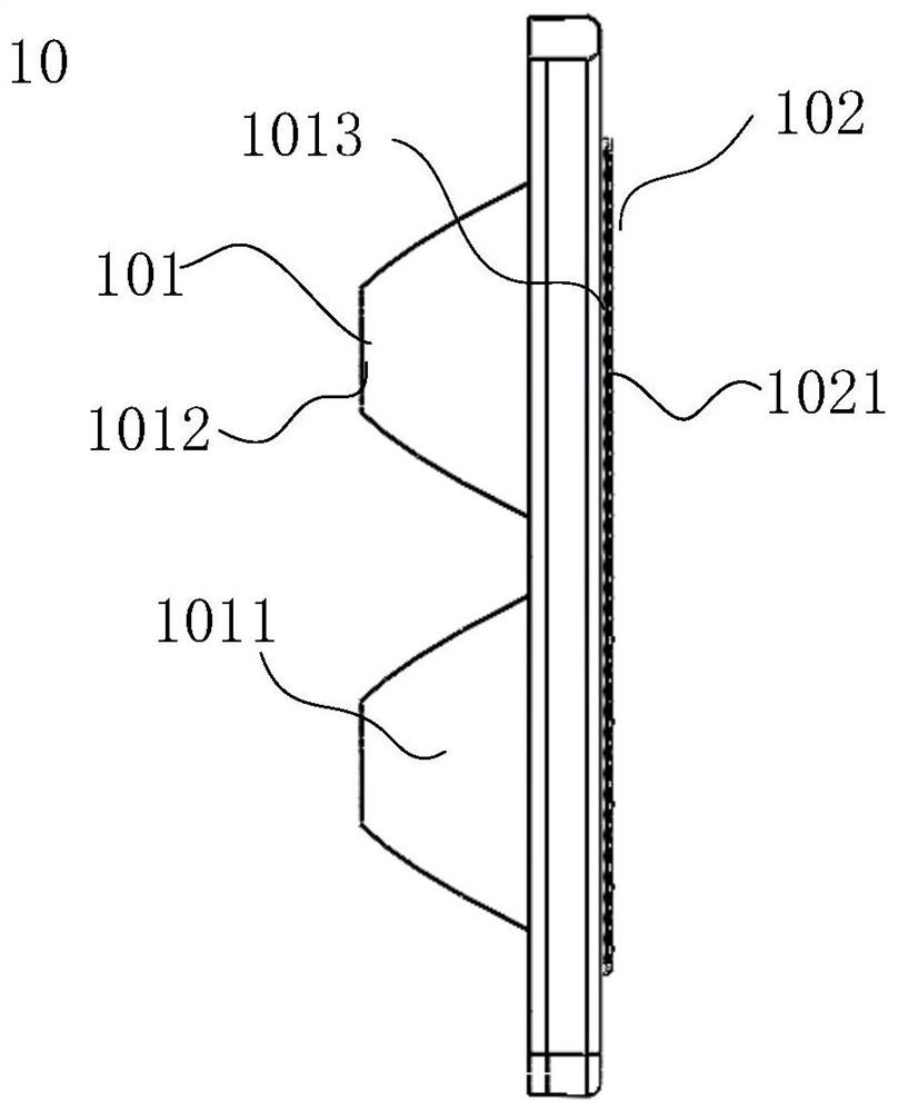
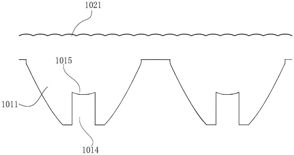
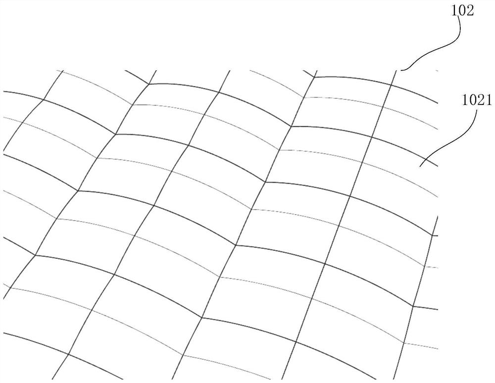
[0036] See Figure 1 to 5 As shown, the light lens assembly 10 in the present embodiment includes a ratio direct lens unit 101 and a complementary eye lens unit 102, and the collimated lens unit 101 is collimated to the light beam emitted by the light source 20, and the complex eye lens unit 102 will be collimated. The processed beam is divided.

[0037] Among them, the collimation process is: the light beam emitted by the light source 20 causes the light beam to disperse, and thereby causing the energy dispersed of the beam, the collimating lens unit 101 is quasi-dispersed to collect energy. The segmentation process is that the complex eye lens unit 102 re-segments the energy of the beam into it in accordance with the desired demand of the final imaging to reselect a few small light sources.

[0038] In the prior art, the collimated lens unit 101 and the complementary eye lens unit 102 are separately disposed such that the light beam after the collimated lens unit 101 processes th...

Embodiment 2

[0049] See figure 1 with Image 6 As shown, the illumination device 100 in this embodiment includes a light source 20, a light lens assembly 10, and a receiving assembly 30, and the light beam emitted by the light source 20 is received after the receiving assembly 30 is received. Among them, the light lens assembly 10 is the light lens assembly 10 shown in Example 1. It is disposed on one side of the light source 20 for collimating and segmenting the light beam of the light source 20. In the present embodiment, the light source 20 is an LED, and the receiving assembly 30 is an LCD.

[0050] The illumination device 100 in the prior art is provided with integral lens assemblies between the light lens assembly 10 and the receiving assembly 30, and the integral lens assembly includes several integral lenses, several integral lenses will be formed by the complex eye lens unit 102. A small light source 20 is superimposed to the receiving assembly 30 to form uniform lighting. However, the...


PUM

PropertyMeasurementUnit
Lengthaaaaaaaaaa

Abstract

The invention relates to an optical lens assembly and a lighting device, and belongs to the technical field of lighting equipment. The optical lens assembly includes: a collimating lens unit; and a fly's-eye lens unit which directly receives the light beams emitted from the collimating lens unit and has the same optical characteristics as the collimating lens unit. The lighting device includes: a light source; the optical lens assembly which is arranged on one side of the light source, wherein the optical lens assembly is used for collimating and segmenting light beams of the light source; and a receiving assembly which is used for receiving the light beams emitted by the optical lens assembly. The fly's-eye lens unit directly receives the light beams emitted by the collimating lens unit, and the optical characteristics of the fly's-eye lens unit and the optical characteristics of the collimating lens unit are kept consistent, so that the light beams are propagated and processed in the lenses with the same optical characteristics in the propagation process, energy loss of the light beams in the propagation process is prevented, and the lighting effect is improved.

Description

[Technical field] [0001] The present application relates to a light lens assembly and a lighting device belonging to the technical field of lighting. 【Background technique】 [0002] With the development of automobile intelligence technology, the cost of head up displaphic, referred to as HUD is lowered, and more and more cars are equipped with a lifted display. The HUD image can be clearly observed in various brightness environments in the outside, so this has highly demanded HUD backlight brightness. At the same time, due to the smaller space interior of the car instrument, the HUD backlight volume also puts forward strict requirements. [0003] The HUD backlighting scheme in the prior art uses a reciprocating lighting solution for conventional projectors, usually the solution includes a collimated system, a diaphragm system, integral lens 3, but the lighting scheme causes light efficiency loss during beam propagation. Therefore, there is thus leading to a high cost, low efficie...

Claims


Application Information

Patent Timeline
IPC IPC(8): G02B27/01G02B3/00G02B27/10G02B27/12
CPCG02B27/0101G02B3/00G02B3/0056G02B27/106G02B27/123G02B2027/013G02B2003/0093
Inventor 苗顺平冉坐
Owner AISPEECH CO LTD
Why Eureka
Try Eureka