Traffic detection system
A technology for traffic detection and detection results, applied in the field of information, can solve the problems of low controllability, many uncertain factors of movement, great traffic pressure, etc., and achieve the effect of improving safety.
- Summary
- Abstract
- Description
- Claims
- Application Information
AI Technical Summary
Problems solved by technology
Method used
Image
Examples
Embodiment 1
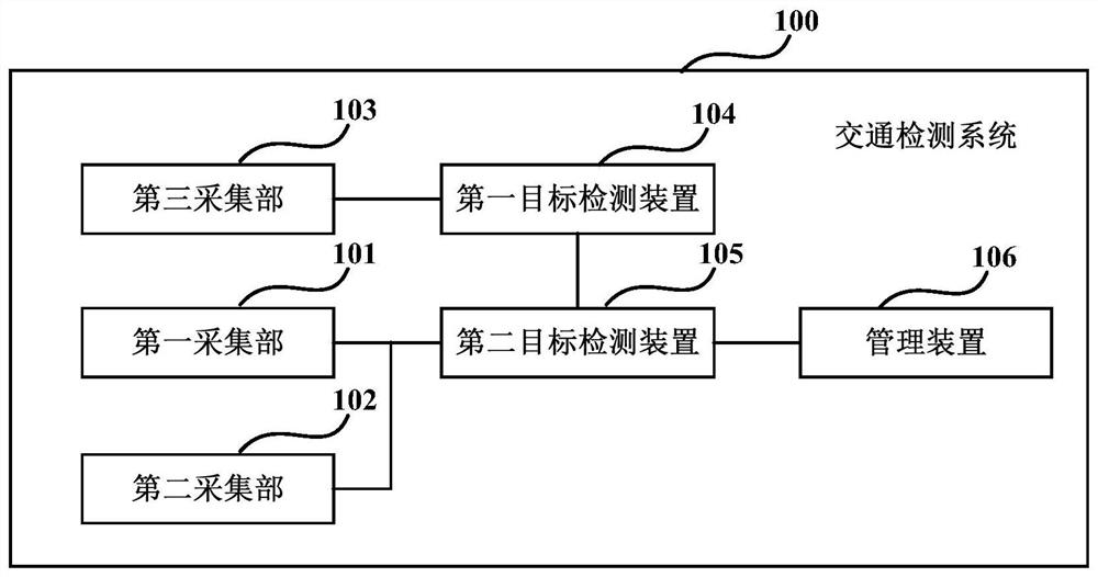
[0027] An embodiment of the present application provides a traffic detection system. figure 1 It is a schematic diagram of the traffic detection system of Embodiment 1 of the present application.
[0028] Such as figure 1 As shown, the traffic detection system 100 includes:
[0029] The first collection unit 101, which obtains the monitoring video of the road;
[0030] The second acquisition unit 102, which transmits radar signals to a preset area of the road and obtains radar reflection signals;
[0031] The third acquisition unit 103 is arranged on the vehicle and obtains the video shot from the perspective of the vehicle;
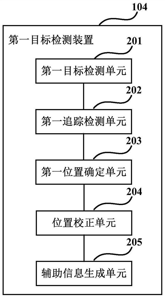
[0032] The first object detection device 104, which obtains the first detection result of the object according to the video taken from the perspective of the vehicle; and
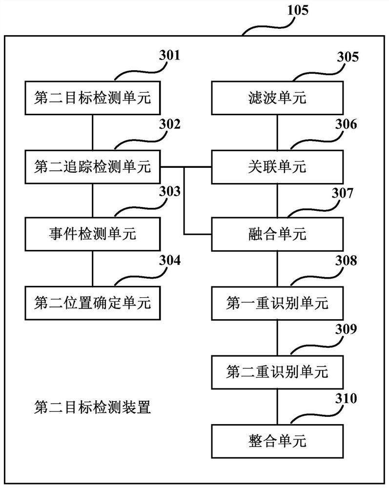
[0033] The second target detection device 105, which obtains the second detection result of the target object according to the monitoring video of the road, and obtains the thir...
Embodiment 2
[0122] The embodiment of the present application also provides an electronic device, Figure 6 It is a schematic diagram of the electronic device of Embodiment 2 of the present application. Such as Figure 6 As shown, the electronic device 600 includes a target detection device 601. The target detection device 601 may be the first target detection device 104 and / or the second target detection device 105 in Embodiment 1, and its specific structure and function are the same as those in Embodiment 1. The records are the same and will not be repeated here.
[0123] In an implementation manner of the embodiment of the present application, the electronic device 600 may be various types of electronic devices, for example, a vehicle-mounted terminal, a mobile terminal, or a server.
[0124] Figure 7 It is a schematic block diagram of the system configuration of the electronic device according to Embodiment 2 of the present application. Such as Figure 7 As shown, the electronic ...
Embodiment 3
[0135] The embodiment of the present application also provides a traffic detection method, which corresponds to the traffic detection system in Embodiment 1. Figure 8 It is a schematic diagram of the traffic detection method in Embodiment 3 of the present application. Such as Figure 8 As shown, the method includes:
[0136] Step 801: Obtain the monitoring video of the road;
[0137] Step 802: Transmitting radar signals to a preset area of the road and obtaining radar reflection signals;
[0138] Step 803: Obtain a video shot from the perspective of the vehicle;
[0139] Step 804: Obtain a first detection result of the target object according to the video taken from the perspective of the vehicle; and
[0140] Step 805: Obtain the second detection result of the target object according to the surveillance video of the road, and obtain the third detection result of the target object according to the radar reflection signal, and integrate the second detection result, the t...
PUM
 Abstract
Description
Claims
Application Information
 - R&D
- Intellectual Property
- Life Sciences
- Materials
- Tech Scout
- Unparalleled Data Quality
- Higher Quality Content
- 60% Fewer Hallucinations
Browse by: Latest US Patents, China's latest patents, Technical Efficacy Thesaurus, Application Domain, Technology Topic, Popular Technical Reports.
© 2025 PatSnap. All rights reserved.Legal|Privacy policy|Modern Slavery Act Transparency Statement|Sitemap|About US| Contact US: help@patsnap.com


