Cable fixing device for smart power grid

A technology of cable fixing device and smart grid, which is applied in the direction of cable suspension device, cable installation, electrical components, etc., can solve the problems of inability to meet user needs, cables cannot be rotated, and use limitations, etc., and improve the use limitations. performance, improve safety, and prolong service life

Inactive Publication Date: 2021-11-23
樊俊俊
View PDF0 Cites 0 Cited by
  • Summary
  • Abstract
  • Description
  • Claims
  • Application Information

AI Technical Summary

Problems solved by technology

[0003] Nowadays, as the pace of China's electric power development continues to accelerate, the smart grid has also developed rapidly, and basically formed a complete long-distance power transmission grid structure. At present, the cables of the smart grid are mainly installed on walls or poles through fixtures. Most of the existing fixing devices use clamps to fix the cables when they are in use, and the angle of the cables after fixing is usually unable to rotate, which leads to the fact that the cables are prone to damage due to the need for torsion during actual use, so the use is limited. High reliability, can not meet the needs of users, therefore, it is necessary to further improve

Method used


Image

  • Cable fixing device for smart power grid
  • Cable fixing device for smart power grid
  • Cable fixing device for smart power grid

Examples


Embodiment Construction

[0027] The following will clearly and completely describe the technical solutions in the embodiments of the present invention in conjunction with the accompanying drawings in the embodiments of the present invention. Obviously, the described embodiments are only some embodiments of the present invention, not all embodiments, and It should be noted that, in the case of no conflict, the embodiments in the present invention and the features in the embodiments can be combined with each other. "The word only means that it is consistent with the upper, lower, left and right directions of the drawing itself, and does not limit the structure. Based on the embodiments of the present invention, those of ordinary skill in the art have obtained it without creative work. All other embodiments of all belong to the protection scope of the present invention.

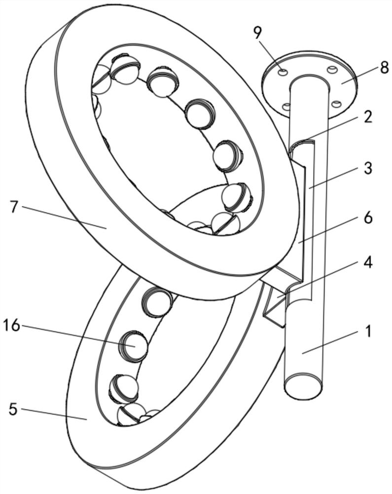
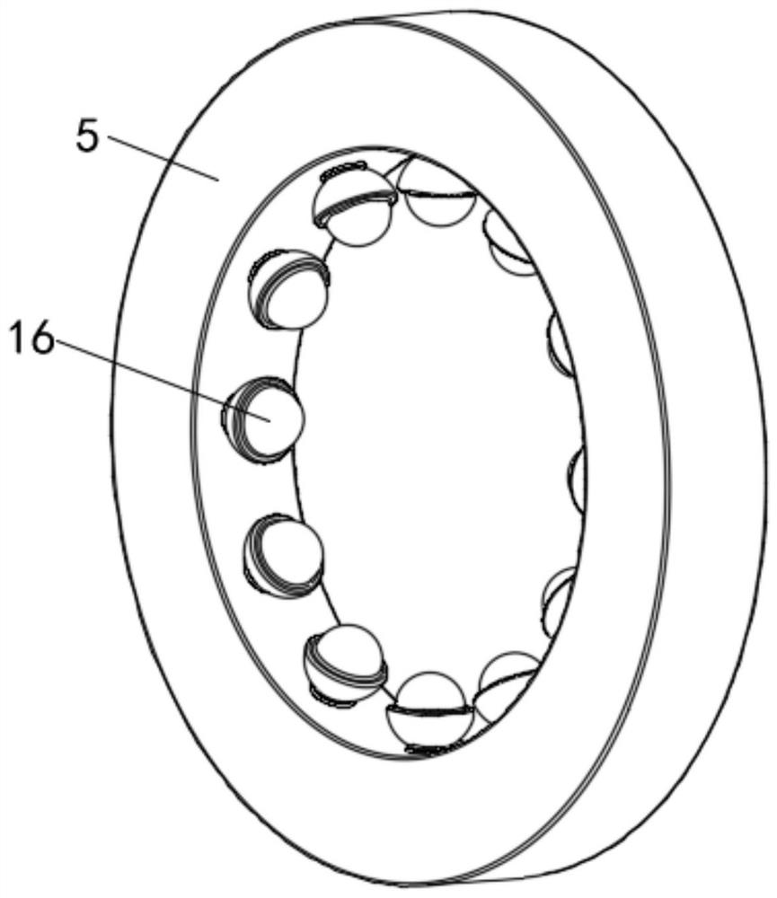
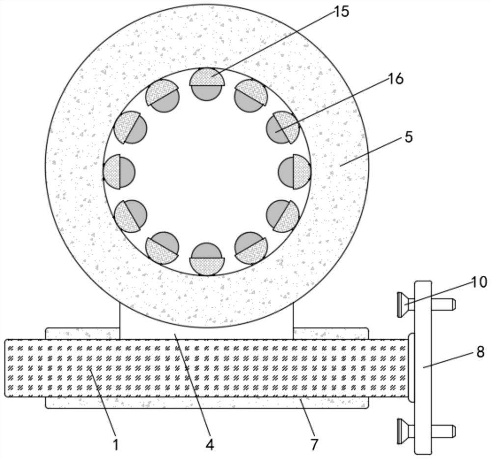
[0028] see Figure 1 to Figure 6 , a cable fixing device for a smart grid, comprising a main body 1, a movable slot 2 is opened on th...


PUM


Abstract

The invention provides a cable fixing device for a smart power grid. The cable fixing device comprises a main body. The main body is provided with a movable groove, and the movable groove is formed in one side of the main body. The movable groove is internally provided with a movable rotating shaft. A first fixing piece is fixedly mounted on the outer side of the main body. A first hoop is fixedly installed on the side, away from the main body, of the first fixing piece. A second fixing piece is fixedly installed on the outer side of the movable rotating shaft. According to the cable fixing device for a smart power grid, clamping balls are arranged on the inner walls of the first hoop and a second hoop, so that on one hand, a cable is prevented from being abraded due to friction with the inner walls of the first hoop and the second hoop when being pulled, and the service life of the cable is prolonged; and on the other hand, the cable can be effectively clamped and protected, the angle of the cable can be adjusted, the use limitation of the cable is improved, and meanwhile, the use effect of the equipment is further improved.

Description

technical field [0001] The invention belongs to the technical field of the smart grid industry, and in particular relates to a cable fixing device for the smart grid. Background technique [0002] The smart grid is regarded as the next generation power grid. It uses information to ensure the custom supply and monitoring of power. In the smart grid, the generated power can be adjusted according to the real-time needs of users, which can not only ensure the satisfaction of user needs, but also To avoid the waste of excess power, a notable feature of the smart grid is the large-scale deployment of various sensors and smart meters. [0003] Nowadays, as the pace of China's electric power development continues to accelerate, the smart grid has also developed rapidly, and basically formed a complete long-distance power transmission grid structure. At present, the cables of the smart grid are mainly installed on walls or poles through fixtures. Most of the existing fixing devices ...

Claims


Application Information

Patent Timeline
Patent Type & Authority Applications(China)
IPC IPC(8): H02G3/32H02G7/05
CPCH02G3/32H02G7/053
Inventor 樊俊俊
Owner 樊俊俊
Why Eureka
Try Eureka