Fertilization device with liquid fertilizer slow release function
A technology of fertilization device and liquid fertilizer, which is applied in the direction of fertilization device, liquid fertilizer distribution, liquid fertilizer adjustment system, etc., can solve the problems of slow release of liquid fertilizer, unfavorable absorption of liquid fertilizer, waste of liquid fertilizer, etc., so as to avoid unnecessary waste and guarantee Fertilization stability and comprehensive effect
Pending Publication Date: 2021-11-26
郑州西格罗丁电子科技有限公司
0 Cites 2 Cited by
AI-Extracted Technical Summary
Problems solved by technology
[0003] The purpose of the present invention is to provide a fertilization device with a slow-release function of liquid fertilizer, to solve the problem that the existing equipment proposed in the above-mentioned background t...
Method used
Further, medicine spraying mechanism 600 includes inner tube 601, and inner tube 601 is fixedly communicated on the outer wall of sleeve pipe 503, and the outer side movable sleeve of inner tube 601 is provided with outer tube 602, and inner tube 601 and outer tube 602 There are seepage holes evenly opened on the outer wall of the inner tube 601, and the seepage holes opened on the outer wall of the inner tube 601 correspond to the seepage holes opened on the outer wall of the outer tube 602, and the outer wall of the inner tube 601 is equipped with a clip, and the clip is embedded In the chute correspondingly opened on the inner wall of the outer tube 602, the inner tube 601 and the outer tube 602 are connected in a sliding telescopic manner. The total amount of elongation between the inner tubes 601 can be adjusted according to the needs of actual use. By pulling the outer tube 602 outward, the coverage area of the inner tube 601 and the outer tube 602 can be flexibly adjusted, which is convenient for flexible control of the device for liquid fertilizers. The release range of the device effectively improves the flexibility of use of the device. At the same time, the outer wall of the inner tube 601 is fixedly installed with clips. Under the fitting restrictions of the clips and the chute, the outer tube 602 and inner tube 601 can only slide left and right to avoid relative rotation between the outer tube 602 and the inner tube 601, thereby avoiding the rotation between the outer tube 602 and the inner tube 601 so that the seepage holes opened on the outer wall are covered and blocked, effectively The stability of the fertilization work of the device is greatly improved.
Further, on the outer wall of cylinder 301, shell 303 is fixedly installed, and the outside of the central axis of valve roller 302 is fixedly connected with worm wheel 304, and worm wheel 304 is connected in the inside of shell 303 in rotation, and the outside of worm wheel 304 is meshed and connected with worm 305, and the worm 305 is rotatably connected to the inside of the housing 303, the outside of the central axis of the worm 305 is fixedly connected with a handle, and the bottom of the cylinder 301 is fixedly connected with a connecting pipe 306. The meshing transmission between the teeth makes the rotating worm 305 drive the worm wheel 304, which can effectively drive the valve roller 302 to rotate. When the external force is applied to rotate, the worm wheel 304 is accidentally rotated to cause the valve roller 302 to rotate, which effectively improves the accuracy of the valve roller 302 being rotated and controlled, and is conducive to ensuring the stability of the valve opening of the valve roller 302. By setting the casing 303 to wrap On the outside of the worm wheel 304 and the worm screw 305, the worm wheel 304 and the worm screw 305 are effectively isolated from the external environment, so as to ensure the stability of the meshing transmission between the worm wheel 304 and the worm screw 305, by setting the fixed connection between the handle and the worm screw 305 , which is conducive to providing a stable rotating force application point for the staff when using the control, and is convenient to improve the control convenience of the flow regulating mechanism 300 .
Further, the rotating mechanism 500 includes a bracket 501, the outer wall of the bottom frame 401 is fixedly connected with the fixed cylinder 502 by the bracket 501, and the outer movable sleeve of the fixed cylinder 502 is provided with a sleeve 503, and on the outer wall of the fixed cylinder 502 Holes and grooves for permeable water are uniformly provided, and the fixed cylinder 502 and the communication pipe 306 are fixedly connected. The outer wall of the casing 503 is fixed with an external gear ring 504, and the outer gear ring 504 is meshed with a rack plate 505 , the rack plate 505 is slidably connected to the outer wall of the bottom frame 401. When the device is working, the rack plate 505 slides up and down, and under the meshing transmission of the teeth, the outer gear ring 504 can drive the casing 503 to rotate. , the rotation of the casin...
Abstract
The invention relates to the technical field of agricultural fertilization, in particular to a fertilization device with a liquid fertilizer slow release function, which comprises a liquid storage tank, the bottom of the liquid storage tank is fixedly connected with an opening and closing mechanism, the bottom of the opening and closing mechanism is fixedly provided with a flow adjusting mechanism, a base is fixedly mounted at the bottom of the flow adjusting mechanism, and pesticide spraying mechanisms are connected to the left side and the right side of the base through rotating mechanisms. The bottom of the liquid storage tank is fixedly communicated with the opening and closing mechanism, a temperature regulation and control mechanism is connected with the opening and closing mechanism, and a stop plate is controlled to move by means of volume expansion or shrinkage of safe gas in a metal gas tank due to temperature change in cooperation with elastic support of a first spring, therefore, liquid fertilizer can be conveniently applied according to the external environment, the absorption efficiency of the liquid fertilizer can be prevented from being influenced by the application of the liquid fertilizer in high-temperature weather, the comprehensiveness of absorption of the released liquid fertilizer can be conveniently guaranteed, and the liquid fertilizer can be effectively prevented from being wasted without reasons.
Application Domain
Manure treatmentLiquid fertiliser regulation systems +2
Technology Topic
FertilizerPesticide +5
Image
Examples
- Experimental program(1)
Example Embodiment
[0030] The technical solutions in the embodiments of the present invention will be clearly and completely described below with reference to the accompanying drawings in the embodiments of the present invention. Obviously, the described embodiments are only a part of the embodiments of the present invention, but not all of the embodiments. Based on the embodiments of the present invention, all other embodiments obtained by those of ordinary skill in the art without creative efforts shall fall within the protection scope of the present invention.
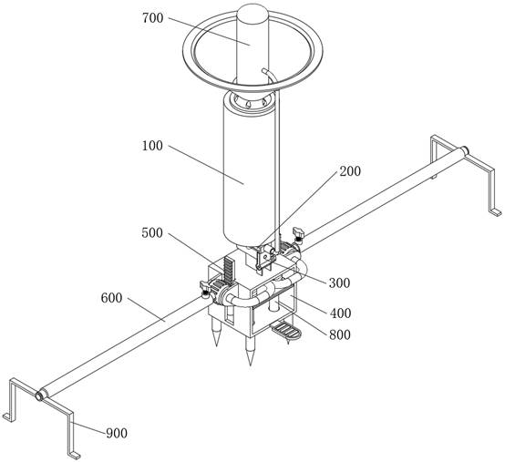
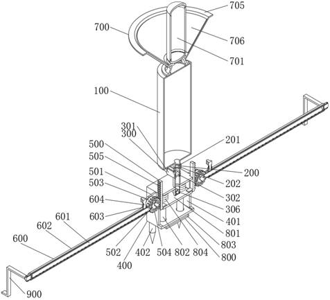
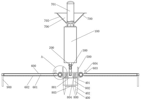
[0031] see Figure 1-10, an embodiment provided by the present invention: a fertilization device with a slow release function of liquid fertilizer, comprising a liquid storage tank 100, the bottom of the liquid storage tank 100 is fixedly connected with an opening and closing mechanism 200, and the bottom of the opening and closing mechanism 200 is fixed The flow regulating mechanism 300 is installed, the bottom of the flow regulating mechanism 300 is fixedly installed with the base 400, and the left and right sides of the base 400 are connected with the spraying mechanism 600 through the rotating mechanism 500, and the top of the liquid storage tank 100 is fixedly installed with a temperature regulating mechanism 700, a trigger mechanism 800 is installed inside the base 400. When the device works, the liquid fertilizer is stored in the liquid storage tank 100, and the release of the liquid fertilizer is controlled by means of the opening and closing mechanism 200 and the temperature control mechanism 700. The flow adjustment mechanism 300 can effectively adjust the rate of feeding liquid fertilizer, and the liquid fertilizer can be actually applied by means of the spraying mechanism 600, and the fertilization coverage of the liquid fertilizer can be adjusted according to the actual demand, and the rotation is driven by the transformation of the setting trigger mechanism 800. The mechanism 500 controls the retracting and retracting of the spraying mechanism 600, which effectively improves the convenience of use of the device.
[0032] The opening and closing mechanism 200, the opening and closing mechanism 200 includes a casing 201, and the casing 201 is fixedly connected to the bottom middle position of the liquid storage tank 100, and a stop plate 202 is inserted laterally inside the casing 201, and the stop plate A through hole is opened in the middle position of 202, and the through hole is located just below the place where the housing 201 communicates with the liquid storage tank 100, the side of the stop plate 202 is laterally fixedly connected with a spring one 203, and the other end of the spring one 203 is fixedly connected On the right inner wall of the casing 201, the stop plate 202 is elastically slidably connected to the casing 201 through a spring 1 203, and the opening and closing mechanism 200 communicates with the spraying mechanism 600 through the flow regulating mechanism 300 and the rotating mechanism 500, When the device is working, the stop plate 202 is movably inserted inside the casing 201. When the stop plate 202 moves inside the casing 201, the movement of the stop plate 202 drives the through hole opened in the device. Move, so that the through hole and the casing 201 are dislocated up and down. Under the dislocation of the through hole, the casing 201 and the stop plate 202 cooperate to terminate the conduction of the liquid fertilizer. In this case, the fertilization operation cannot be performed. When there is no external force When applied on the stopper plate 202, the stopper plate 202 is pushed and reset by the elastic deformation of the spring 1 203. At this time, when the stopper plate 202 drives the through hole to move to the initial position, the through hole is connected. The connection between the upper and lower sides of the casing 201 makes the upper liquid fertilizer conduct and flow downward, and the stop plate 202 slides left and right inside the casing 201 to control the conduction and cut-off of the liquid fertilizer, which is beneficial to the device according to the time of use. According to the actual situation of fertilization and application, the operation is flexible and convenient.
[0033] The temperature-controlled mechanism 700 includes a metal gas tank 701, and the metal gas tank 701 is fixedly installed on the top of the liquid storage tank 100. The inside of the metal gas tank 701 is filled with an appropriate amount of safe gas. The outer wall of 701 is communicated with a barrel 702 through a pipeline, and the barrel 702 is fixedly connected to the side of the outer wall of the housing 201 away from the spring 1 203. The inner of the barrel 702 is movably inserted with a push rod 703, and the push rod 703 One end is fixedly connected with the stop plate 202, the other end of the push rod 703 is fixedly installed with a valve plate 704, and the outer dimension of the valve plate 704 is matched with the inner dimension of the cylinder body 702, and the valve plate 704 and the cylinder body 702 are connected. When the device is in operation, since the inside of the metal gas tank 701 is filled with safe gas, and because the device is set up between fields to slowly release liquid fertilizers, affected by the terrain environment, the temperature difference between day and night in the fields changes in a large range. When the external ambient temperature is high, at this time, referring to the daytime in a high temperature state, under the influence of the external high temperature weather, the temperature inside the metal gas tank 701 increases, and under the action of high temperature, the internal temperature of the metal gas tank 701 is increased. The volume of the safe gas is heated and expanded, and the expanded gas pushes the valve plate 704 embedded in the cylinder body 702 along the pipeline. Under the push of the gas expansion, the valve plate 704 is pushed, and the push rod 703 is driven to move, thereby making the stop plate 202 Pushed by the push rod 703 to move in the interior of the housing 201, through the movement of the stopper plate 202, the through holes opened in it move and then dislocate. The housing 201 and the stopper plate 202 cooperate with each other to block the downward flow of the main liquid fertilizer. , so that when the outside temperature is high, there is no active fertilization operation, so as to avoid the high temperature weather affecting the efficiency of liquid fertilizer being absorbed by crops. Under the influence of the environment, the temperature inside the metal gas tank 701 is lowered. Affected by the temperature drop, the volume of the safe gas charged into the Shudie metal gas tank 701 gradually shrinks, and the gas after the volume shrinkage loses its support to the valve plate inside the cylinder body 702. The pushing force of 704, at this time, under the action of the elastic deformation reset support of the spring 1 203, the stop plate 202 is pushed back and reset, and after the stop plate 202 is reset, the through holes inside the stop plate 202 are reconnected to the upper and lower ends of the housing 201 , it is convenient to control the downward application of liquid fertilizer, and the application of liquid fertilizer in low temperature weather is conducive to the absorption of crops. By using the gas inside the metal gas tank 701 to be cooled or heated, the device can be flexibly controlled by changing the external environment. The application and cut-off of liquid fertilizer is beneficial to avoid continuous application of liquid fertilizer in high temperature weather, affecting the absorption effect of crops on fertilizer, and avoiding the waste of fertilizer for no reason. At the same time of the absorption efficiency of fertilizer, it can also effectively prolong the application time of the same amount of fertilizer, which is convenient for slow-controlled fertilization operation.
[0034] Further, the flow regulating mechanism 300 includes a cylinder 301 , and the cylinder 301 is fixedly connected to the bottom of the casing 201 , and the connection between the cylinder 301 and the casing 201 and between the liquid storage tank 100 and the casing 201 The connection point of the cylinder 301 is located on the same vertical line, the inside of the cylinder 301 is rotatably connected with the valve roller 302, and the middle position of the valve roller 302 is vertically penetrated with a valve port, and the valve port is located in the cylinder 301 and communicates with the shell 201 When the device is working, the valve roller 302 is set to rotate and connect to the inside of the cylinder 301. With the help of the rotation of the valve roller 302, the inclination angle of the valve port inside the valve roller 302 can be controlled, and the inclination of the valve port can be dislocated. , the actual opening diameter between the valve port and the connection on the cylinder 301 can be controlled, which is convenient to flexibly control the overall application speed of the liquid fertilizer of the device by rotating the valve roller 302, and it is convenient for the staff to flexibly adjust according to the actual needs of use.
[0035] Further, a casing 303 is fixedly installed on the outer wall of the cylinder 301, a worm gear 304 is fixedly connected to the outside of the central axis of the valve roller 302, and the worm gear 304 is rotatably connected to the inside of the casing 303, and a worm 305 is meshed and connected to the outside of the worm gear 304, and The worm 305 is rotatably connected to the inside of the casing 303, the outer side of the central axis of the worm 305 is fixedly connected with a handle, and the bottom of the cylinder 301 is fixedly connected with a communication pipe 306. The tooth meshing transmission, so that when the rotating worm 305 drives the worm wheel 304, the valve roller 302 can be effectively rotated and driven, and at the same time, by means of the tooth meshing between the worm 305 and the worm wheel 304 Self-locking, so that the worm 305 is not applied by external force During rotation, the worm wheel 304 is accidentally rotated, causing the valve roller 302 to rotate, which effectively improves the accuracy of the rotation control of the valve roller 302, and helps to ensure the stability of the valve opening range of the valve roller 302. and the outside of the worm 305, effectively isolate the worm wheel 304 and the worm 305 from the external environment, so as to ensure the stability of the meshing transmission between the worm wheel 304 and the worm 305. By setting the fixed connection between the handle and the worm 305, it is beneficial to It provides a stable rotational force application point for the staff when using and controlling, which is convenient to improve the convenience of regulation of the flow regulating mechanism 300 .
[0036] Further, the base 400 includes a bottom frame 401, the bottom frame 401 is fixedly welded on the bottom of the cylinder 301, the communication pipe 306 runs through the top of the bottom frame 401, and the bottom four corners of the bottom frame 401 are vertically fixed with pins 402, A pedal is symmetrically fixed on the outer side of the bottom of the bottom frame 401. When the device is working, a pin 402 is fixedly installed at the bottom of the bottom frame 401. The staff presses the device downward, so that the pin 402 breaks the soil and is inserted inside the ground. , so that the device is fixedly installed on the ground, which is convenient to ensure the stability of the device when it is working. At the same time, the pedals are symmetrically fixed on the outer side of the bottom of the bottom frame 401, which is convenient to provide the working point for the staff to step on the force. , so that the device can be more easily inserted into the ground.
[0037] Further, the rotating mechanism 500 includes a bracket 501, the outer wall of the bottom frame 401 is fixedly connected with a fixing cylinder 502 through the bracket 501, and the outer side of the fixing cylinder 502 is movably sleeved with a sleeve 503, and the outer wall of the fixing cylinder 502 is evenly opened with useful The fixed cylinder 502 and the communication pipe 306 are in fixed communication with the holes and grooves for permeable water. The outer wall of the sleeve 503 is surrounded and fixed with an external gear ring 504, and the outer side of the external gear ring 504 is meshed and connected with a rack plate 505. The plate 505 is slidably connected to the outer wall of the bottom frame 401. When the device works, the rack plate 505 slides up and down to move. Under the meshing transmission of the teeth, the outer gear ring 504 can drive the sleeve 503 to rotate. The rotation of the tube 503 can drive the spraying mechanism 600 connected to the outside thereof to swing, which is convenient for retracting and retracting the spraying mechanism 600, which is beneficial for the device to be converted by bending, reduces the overall space occupied by the device, and facilitates the storage and transportation of the device. , by setting the sleeve 503 to rotate and sleeve on the outside of the fixed cylinder 502, and set the fixed cylinder 502 and the sleeve 503 to communicate through holes and grooves, so that the fixed cylinder 502 and the sleeve 503 can always be kept in communication when rotating. In this state, it is convenient to ensure the fertilization stability of the device, avoid the influence of the connection of the liquid fertilizer being affected by the rotation of the fixed cylinder 502 and the sleeve 503, and effectively ensure the working stability of the device.
[0038] Further, the spraying mechanism 600 includes an inner tube 601, and the inner tube 601 is fixedly connected to the outer wall of the sleeve 503, and the outer side of the inner tube 601 is movably sleeved with an outer tube 602, and the outer walls of the inner tube 601 and the outer tube 602 are The seepage holes are evenly opened, and the seepage holes opened on the outer wall of the inner tube 601 correspond to the seepage holes opened on the outer wall of the outer tube 602, and the outer wall of the inner tube 601 is equipped with a clip, and the clip is embedded in the outer tube 602. In the corresponding chute on the inner wall, the inner tube 601 and the outer tube 602 are connected by sliding and telescopic. The total amount of elongation between the two can be adjusted according to the actual needs of use. By pulling the outer tube 602 outward, the coverage area of the inner tube 601 and the outer tube 602 can be flexibly adjusted, which is convenient to flexibly control the release range of the device for liquid fertilizer. , which effectively improves the flexibility of the device. At the same time, by arranging a clip on the outer wall of the inner tube 601, under the restriction of the clip and the chute, the gap between the outer tube 602 and the inner tube 601 is reduced. It can only slide left and right to avoid relative rotation between the outer tube 602 and the inner tube 601, so as to avoid the rotation between the outer tube 602 and the inner tube 601, so that the seepage holes opened on the outer wall are blocked and blocked, which effectively improves the The stability of the device's fertilization work.
[0039] Further, a nut 603 is fixedly installed on the outer wall of the outer tube 602 at a position close to the sleeve 503, and a bolt 604 is inserted inside the nut 603, and the thread assembled on the outer wall of the bolt 604 is compatible with the thread assembled on the inner wall of the nut 603. The bolt 604 and the nut 603 are connected by threaded engagement. When the device works, it is fixedly installed on the outer wall of the outer tube 602 by setting the nut 603. When the relative elongation of the outer tube 602 and the inner tube 601 is adjusted by sliding , the worker rotates the bolt 604, under the meshing action of the thread, the bolt 604 moves inside the nut 603, and after the nut 603 moves, it is squeezed on the outer wall of the inner tube 601, so that the inner tube 601 and the outer tube 602 The position of the device is fixed, so as to ensure the stability of the outer tube 602 of the device after the extension and adjustment.
[0040]Further, a condensing cover 705 is fixedly installed on the top of the liquid storage tank 100, and the condensing cover 705 is arranged on the outer side of the bottom of the metal gas tank 701. A reflective sticker 706 is fixedly attached to the inner wall of the metal gas tank 706, and the bottom of the condensing cover 705 is evenly provided with drainage holes. A reflective sticker 706 is attached to the inner wall of the mask 705. During operation, the reflective sticker 706 gathers the light in the external environment, so that the metal gas tank 701 in the middle position can be irradiated with more sunlight, thereby The temperature inside the metal air tank 701 is more likely to rise during the hot daytime, so as to control the device to stop the application of liquid fertilizer, and the reflective panel 706 concentrates sunlight and temperature, making the device more responsive during the daytime. Sensitive and convenient for more timely and effective slow-release operation of liquid fertilizers.
[0041] Further, the trigger mechanism 800 includes an upper plate 801 , and the upper plate 801 is slidably connected inside the bottom frame 401 , the upper plate 801 is fixedly connected with the rack plate 505 , and the bottom of the upper plate 801 is fixedly connected by the connecting rod 802 . There is a lower plate 803, the connecting rod 802 movably runs through the bottom of the bottom frame 401, the top of the upper plate 801 is fixedly installed with a spring two 804, and the other end of the spring two 804 is fixedly connected to the top of the bottom frame 401, the upper plate 801 is connected by the spring The second 804 is elastically connected with the bottom frame 401. When the device works, the lower plate 803 and the upper plate 801 are connected to the upper and lower ends of the connecting rod 802, and the upper plate 801 and the rack plate 505 are fixedly connected. , so that when the device is embedded in the ground, under the support of the ground, the lower plate 803 pushes the upper plate 801 to move upward through the connecting rod 802, thereby driving the rack plate 505 to move upward, providing power for the rack plate 505. When the device is pulled out, the upper plate 801 is reset under the elastic support and deformation reset action of the second spring 804, which drives the rack plate 505 to move in the opposite direction, and the upper plate 801 moves up and down to provide power drive, so that the device can be When installed and later retracted, it can provide corresponding drive to the rack plate 505 according to the actual situation during use, so that the spraying mechanism 600 can be automatically retracted and unfolded, thereby effectively improving the convenience of the device in use. .
[0042] Further, a bracket 900 is installed on the outer end of the outer tube 602, and the shape of the bracket 900 is a "ji" shape, and the bracket 900 and the outer tube 602 are rotatably connected. 900 can assist the outer end of the outer tube 602 to support, so as to ensure that the extended outer tube 602 can work more stably. , the bracket 900 can be stored toward the liquid storage tank 100 by rotating, so as to avoid increasing the space occupied by the device when the bracket 900 faces the outside when the device is stowed.
[0043] Working principle: When the device is working, the worker inserts the device between the fields where the slow-release liquid fertilizer is to be carried out. The worker rotates the bracket 900 so that the opening of the bracket 900 faces outwards, and then erects the device on the ground. The pin 402 is inserted into the ground by means of stepping on the pedal to exert force.
[0044] During operation, the pins 402 are embedded in the ground to cooperate with the bottom frame 401 to support the device. Simultaneously, when the bottom frame 401 moves downward, the lower plate 803 is squeezed by the relative movement of the ground, and is driven up by the connecting rod 802. The plate 801 moves upward relative to the bottom frame 401, and drives the rack plate 505 to move upward relative to the bottom frame 401. At this time, the sleeve 503 is rotated by means of the gear meshing transmission between the rack plate 505 and the outer gear ring 504. , put down the spraying mechanism 600 so that the spraying mechanism 600 is flush with the ground as a whole, and the bracket 900 is supported on the ground.
[0045] When working, the worker stretches the outer tube 602 outward, so that the outer tube 602 moves outward relative to the inner tube 601. When the outer tube 602 is adjusted to the proper position, the worker rotates the bolt 604 and engages with the thread. Actuated so that the bolt 604 moves inside the nut 603 , presses the outer surface of the inner tube 601 , and fixes the position of the outer tube 602 .
[0046] When working, the worker drives the worm 305 to rotate by rotating the handle, and by means of the teeth meshing between the worm 305 and the worm wheel 304, the casing 303 is rotated, the inclination angle of the valve port inside the casing 303 is adjusted, and the overall liquid fertilizer of the device is controlled. flow velocity.
[0047] During operation, when the external environment is in high temperature weather, the temperature inside the metal gas tank 701 is increased due to the influence of the high temperature weather. Under the action of high temperature expansion, the gas inside the metal gas tank 701 is heated and expanded, and the inside of the cylinder body 702 is pushed up. The embedded valve plate 704, under the connection action of the push rod 703, pushes the stop plate 202. At this time, the through holes inside the stop plate 202 are dislocated and offset, and the conduction is terminated. In this state, the device cannot perform liquid flow. Fertilizer application.
[0048] During work, when the outside world is in the daytime, the reflective panel 706 can effectively collect sunlight and improve the response sensitivity of the device.
[0049] During operation, when the external environment is in low temperature weather, affected by the temperature change, the temperature inside the metal gas tank 701 decreases, the internal gas volume shrinks, and the valve plate 704 embedded in the cylinder body 702 loses its push, so that the stop plate 202 Loss of the gas external force support, under the elastic deformation and reset action of the spring 1 203, the stop plate 202 is reset, and the through hole inside the stop plate 202 is re-conducted at the upper and lower connection positions of the casing 201, so that the device is in a low temperature environment. The liquid fertilizer application operation is carried out at the bottom, and the slow-release operation of the liquid fertilizer is carried out.
[0050] During operation, after the fertilization of the device is completed, the worker adjusts the outer tube 602 and the inner tube 601 to shrink the space between the outer tube 602 and the inner tube 601, and rotates the bracket 900 to turn over to the liquid storage tank 100, then, the worker pulls out the device upwards, Under the elastic support of the second spring 804, the upper plate 801 moves downward relative to the bottom frame 401, and drives the rack plate 505 to move downward relative to the bottom frame 401, so that the spraying mechanism 600 is automatically turned over and vertically retracted. The above is: The entire working principle of the present invention.
[0051] It will be apparent to those skilled in the art that the present invention is not limited to the details of the above-described exemplary embodiments, but that the present invention may be embodied in other specific forms without departing from the spirit or essential characteristics of the invention. Therefore, the embodiments are to be regarded in all respects as illustrative and not restrictive, and the scope of the invention is to be defined by the appended claims rather than the foregoing description, which are therefore intended to fall within the scope of the claims. All changes within the meaning and scope of the equivalents of , are included in the present invention. Any reference signs in the claims shall not be construed as limiting the involved claim.
PUM


Description & Claims & Application Information
We can also present the details of the Description, Claims and Application information to help users get a comprehensive understanding of the technical details of the patent, such as background art, summary of invention, brief description of drawings, description of embodiments, and other original content. On the other hand, users can also determine the specific scope of protection of the technology through the list of claims; as well as understand the changes in the life cycle of the technology with the presentation of the patent timeline. Login to view more.
Similar technology patents
Composition containing ectoin and applications of composition in laser cosmetology
PendingCN111714396AImprove preventive efficacycomprehensive protection
Owner:BLOOMAGE BIOTECHNOLOGY CORP LTD
Horizontal inclined shaft rail safe car arresting system
ActiveCN105799730Acomprehensive protectionReduce impact damage
Owner:HUAINAN MINING IND GRP
Movable guide rail of intelligent robot for workshop
InactiveCN111958637Acomprehensive protectionavoid resistance
Owner:河南美聚生物科技有限公司
Bed unit disinfection device
PendingCN114848868Acomprehensive protectionSimple, convenient and effective disinfection
Owner:深圳市大复科技有限公司
Adaptive regulation and interactive auxiliary walking robot
Owner:WUHU HAILIAN MACHINERY INSTALLATION
Classification and recommendation of technical efficacy words
- comprehensive protection
- avoid unnecessary waste
Taxi dispatching method and taxi dispatching system on basis of video monitoring system
ActiveCN102867411Acomprehensive protection
Owner:ENC DATA SERVICE CO LTD
Intelligent protection system
InactiveCN102118022Acomprehensive protection
Owner:BAODING HEREFAR ELECTRICAL TECH
Composition containing ectoin and applications of composition in laser cosmetology
PendingCN111714396AImprove preventive efficacycomprehensive protection
Owner:BLOOMAGE BIOTECHNOLOGY CORP LTD
Solar energy electric vehicle charging station
InactiveCN104348191Aavoid investmentavoid unnecessary waste
Owner:TIANJIN YONGMING NEW ENERGY TECH
Water heating energy conservation system
Owner:格瑞耐特(天津)环保技术有限公司
I-PON-based data service processing method and system
Owner:BEIJING JISHI HUITONG TECH CO LTD
Gateway device, method for controlling radio transmission, and radio communication system
InactiveCN102057741Aavoid unnecessary waste
Owner:FUJITSU LTD
Device for automatically collecting horn shavings
InactiveCN103262808Aavoid unnecessary waste
Owner:BEIJING FORESTRY UNIVERSITY