
Combined lever frame trailer

A combined type, frame technology, applied in the direction of motor vehicles, goods transport vehicles, loading and unloading vehicle arrangements, etc., can solve the problem of labor-intensive, and achieve the effect of reducing labor, strong practicability, and reducing waste.

Pending Publication Date: 2021-11-26
西安汽车职业大学
View PDF9 Cites 1 Cited by
  • Summary
  • Abstract
  • Description
  • Claims
  • Application Information

AI Technical Summary

Problems solved by technology

[0006] The purpose of the present invention is to provide a combined lever frame trailer, because in the prior art, when carrying goods and dragging motorcycles, many people are required to cooperate to complete the loading and unloading process, which consumes a lot of labor.

Method used


Image

  • Combined lever frame trailer
  • Combined lever frame trailer
  • Combined lever frame trailer

Examples


Embodiment 1

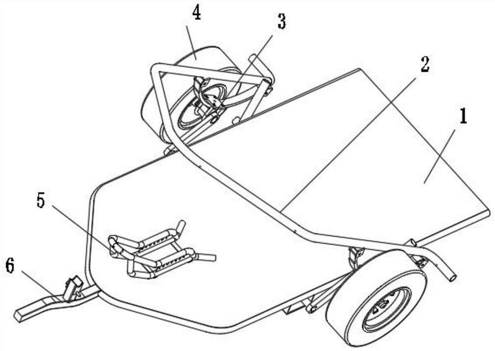
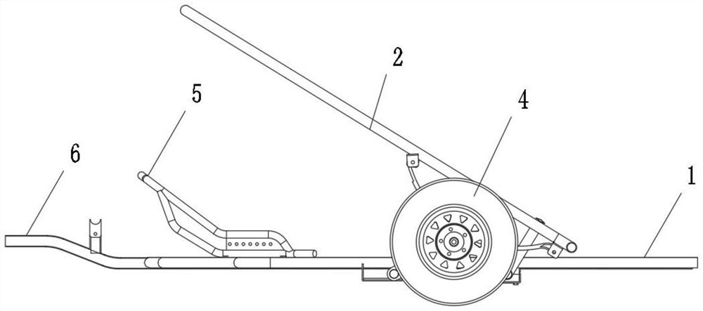
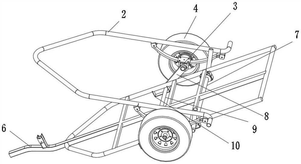
[0030] Such as figure 1 , 2 As shown, the embodiment of the present invention provides a combined lever frame trailer, comprising: a frame on which a bottom plate 1 is arranged; two sliding assemblies 10 are arranged oppositely at the bottom of the frame; A support shaft 9 is arranged between them, and the end of the support shaft 9 passes through the sliding assembly 10 and is connected with a connecting rod 8, and the axis of the connecting rod 8 and the support shaft 9 is perpendicular; the end of the connecting rod 8 away from the support shaft 9 is connected with the rolling assembly 4 , the rotating shaft of the rolling assembly 4 and the end of the connecting rod 8 away from the supporting shaft 9 are fixed; a lever structure 3 is also included, the power arm 2 of the lever structure 3 is arranged above the vehicle frame, and the fulcrum structure of the lever structure 3 is arranged on the rotating shaft of the rolling assembly 4 On, the resistance arm of lever struct...

Embodiment 2

[0035] On the basis of Embodiment 1, in order to make the force at the point of action of the resistance arm more balanced, one end of the resistance arm of the lever structure 3 away from the fulcrum structure is connected with a support rod 7 through a connecting piece, and the support rod 7 is erected on the vehicle through a bracket. bottom of the shelf.

Embodiment 3

[0037] On the basis of embodiment 1, when carrying out consignment to motorcycle, be provided with the position-limiting structure I5 ​​that is used to limit the movement of wheel on the bottom plate 1 top, position-limiting structure I5 ​​comprises two support frames that are arranged oppositely, and the position-limiting structure I5 ​​of support frame The bottom and the bottom plate are fixed, the end of the support frame away from the rear of the frame is closed, and the end close to the rear of the frame is open, wherein the two support frames are correspondingly provided with vertically arranged connecting plates, and the connecting plates are provided with A plurality of holes, between the two corresponding holes on the two connecting plates, is used to install the limiting structure II to prevent the rotation of the wheel. In the hole, to adapt to the limit of the wheels of different diameters.

[0038] Wherein, a traction structure 6 is also included, and the traction...


PUM


Abstract

The invention relates to a combined lever frame trailer which comprises a frame provided with a bottom plate; two sliding assemblies which are oppositely arranged at the bottom of the frame; a supporting shaft which is arranged between the two sliding assemblies, the end of the supporting shaft penetrates through the sliding assemblies and then is connected with a connecting rod, and the connecting rod is perpendicular to the axis of the supporting shaft. One end, away from the supporting shaft, of the connecting rod is connected with a rolling assembly. A rotating shaft of the rolling assembly is fixed to the end, away from the supporting shaft, of the connecting rod. The combined lever frame trailer further comprises a lever structure. A power arm of the lever structure is arranged above the frame, a fulcrum structure of the lever structure is arranged on a rotating shaft of the rolling assembly, and a resisting arm of the lever structure is connected with the rear end of the frame. The device reduces labor force, reduces time waste, and is high in practicability and worthy of popularization.

Description

technical field [0001] The invention relates to the field of vehicle consignment devices, in particular to a combined lever frame trailer. Background technique [0002] With the development of society and the improvement of people's quality of life, every household has a car. For people in rural areas, even if they don't drive a car, they also have a motorcycle. [0003] Especially in recent years, in order to save energy, reduce emissions, and protect the environment in big cities, the number of motorcycles in the city has increased, and traffic accidents often occur. Therefore, incidents of consignment of motorcycles also often occur. [0004] Existing trailers are all aimed at the transportation of medium and large vehicles such as automobiles. They are used for the consignment of motorcycles, which is overkill. Secondly, the motorcycles have two wheels. Multiple people lift the motorcycle and put it on the trailer. This process is time-consuming and labor-intensive, and...

Claims


Application Information

Patent Timeline
IPC IPC(8): B62D63/06B62D63/08B60P3/077B60P1/43
CPCB62D63/062B62D63/08B60P3/077B60P1/433Y02T10/40
Inventor 吕伟王放谢敬尧冯腾飞杨明慧魏玲霞曹亚楠苏娜孙燕妮
Owner 西安汽车职业大学
Learn More