Rolling bearing unit

A technology for rolling bearings and rolling elements, which is applied in the field of bearings and can solve problems such as the complex cost of the bearing condition monitoring system

Pending Publication Date: 2021-11-26
SCHAEFFLER TECH AG & CO KG
View PDF1 Cites 0 Cited by
  • Summary
  • Abstract
  • Description
  • Claims
  • Application Information

AI Technical Summary

Problems solved by technology

However, bearing condition monitoring systems for cages are complex and costly

Method used


Image

  • Rolling bearing unit
  • Rolling bearing unit
  • Rolling bearing unit

Examples


Embodiment Construction

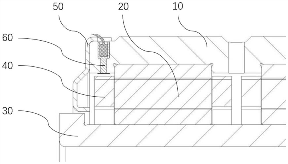
[0028] figure 1 A detail of a cross-sectional view of a rolling bearing unit according to a preferred embodiment is shown. The rolling bearing unit according to the present embodiment can be used for rail transportation vehicles such as subway trains. Such as figure 1 As shown, the rolling bearing unit includes a rolling bearing, a cage condition monitoring assembly 60 and a sealing member 50 .

[0029] The rolling bearing is used here as a wheel set bearing and is embodied in this embodiment as a double-row cylindrical roller bearing. The seal member 50 is provided on the axial end side of the rolling bearing. The rolling bearing comprises an outer ring 10 , an inner ring 30 , two rows of rolling elements 20 in the form of cylindrical rollers and two cages 40 .

[0030] The rolling elements 20 and the cage 40 are arranged radially between the outer ring 10 and the inner ring 30 . Each row of rolling elements 20 is respectively equipped with a cage 40 , and each rolling ele...


PUM


Abstract

The invention relates to a rolling bearing unit comprising a rolling bearing and retainer condition monitoring assemblies (60 and 70). The rolling bearing comprises an outer ring (10), a retainer (40)and at least one row of rolling bodies (20), the inner circumferential surface of the outer ring is provided with a flange portion, the retainer is arranged concentrically on the radially inner side of the outer ring and forms a radial clearance relative to the flange portion during normal operation. The retainer condition monitoring assemblies (60 and 70) comprise light-tight coatings (62 and 72) partially arranged at the inner circumferential surface of the flange portion and capable of being worn by contact of the retainer during abnormal operation; and optical sensors (61 and 71) are arranged in containing holes (11) located in the outer ring, the optical sensors can emit emitted light towards the light-tight coatings and detect reflected light of the emitted light reflected at the light-tight coatings, and when the reduction amount of the reflected light reaches a threshold value along with wear of the light-tight coatings, it can be judged that the retainer fails.

Description

technical field [0001] The invention relates to the technical field of bearings. The invention relates in particular to a rolling bearing unit with a cage condition monitoring assembly. Background technique [0002] Effective condition monitoring and fault diagnosis of rolling bearings are of great significance for ensuring the safe operation of machinery and saving costs. Currently, in a class of bearing condition monitoring systems, early failures of bearings can be detected by finding bearing fatigue. In another common type of bearing condition monitoring system, the raceway wear of the bearing can be monitored by means of vibration measurement, but the calculation in this type of monitoring scheme is complex and the overall cost of the monitoring system is high. [0003] However, the above-mentioned bearing condition monitoring system cannot effectively monitor the condition of the cage. Therefore, even if the cage is severely worn or broken, abnormality of the cage m...

Claims


Application Information

Patent Timeline
Patent Type & Authority Applications(China)
IPC IPC(8): F16C19/38F16C33/58F16C33/48F16C33/30G01N21/95
CPCF16C19/38F16C33/583F16C33/48F16C33/30G01N21/95
Inventor 蔡福强吴丽娟刘志恒贾宪林
Owner SCHAEFFLER TECH AG & CO KG
Why Eureka
Try Eureka