
Integrated electromagnetic protective bearing device

A bearing protection, integrated technology, applied in magnetic bearings, bearings, shafts and bearings, etc., can solve the problems of slow response speed and complex structure of the bearing protection device, and achieve the effect of simplified structure, multiple functions and fast response speed.

Active Publication Date: 2020-08-07
JIANGSU UNIV OF TECH
View PDF7 Cites 2 Cited by
  • Summary
  • Abstract
  • Description
  • Claims
  • Application Information

AI Technical Summary

Problems solved by technology

[0004] In order to solve the technical problems of slow response speed and complex structure of the protection bearing device in the prior art, the present invention proposes an integrated electromagnetic protection bearing device, which solves the above technical problems

Method used


Image

  • Integrated electromagnetic protective bearing device
  • Integrated electromagnetic protective bearing device
  • Integrated electromagnetic protective bearing device

Examples


Embodiment 1

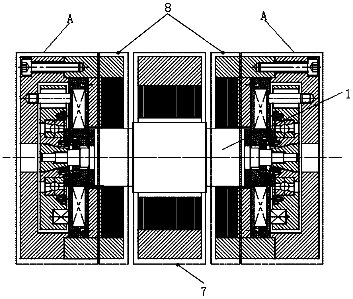
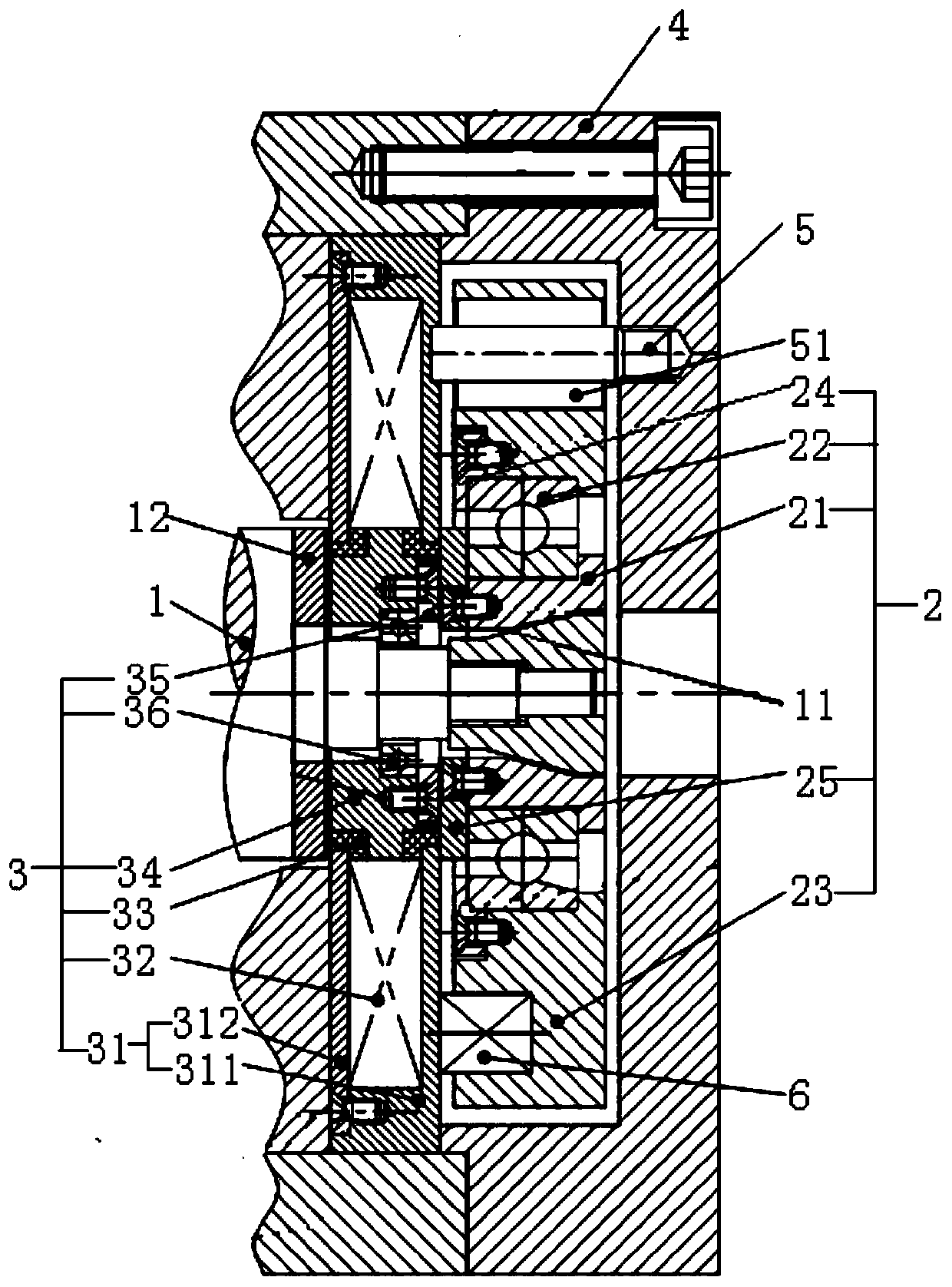
[0031] Such as Figure 1-3 As shown, this embodiment provides an integrated electromagnetic protection bearing device, which is installed at both ends of the rotor 1. Under normal circumstances, the role of electromagnetic adsorption force in the radial magnetic bearing 8 and the integrated electromagnetic protection bearing device Next, the rotor 1 can be in the center position in the radial direction and the axial direction, and rotate at high speed under the action of the motor 7; when the magnetic levitation system is powered off or fails, the integrated electromagnetic protection bearing device can support the rotor 1 , to protect the role of radial magnetic bearing 8. Such as figure 1 As shown, the motor 7 is located in the middle of the rotor 1, the two radial magnetic bearings 8 are symmetrically arranged on both axial sides of the motor 7, and the integrated electromagnetic protection bearing device A is symmetrically arranged on the axial outer side of the two radia...

Embodiment 2

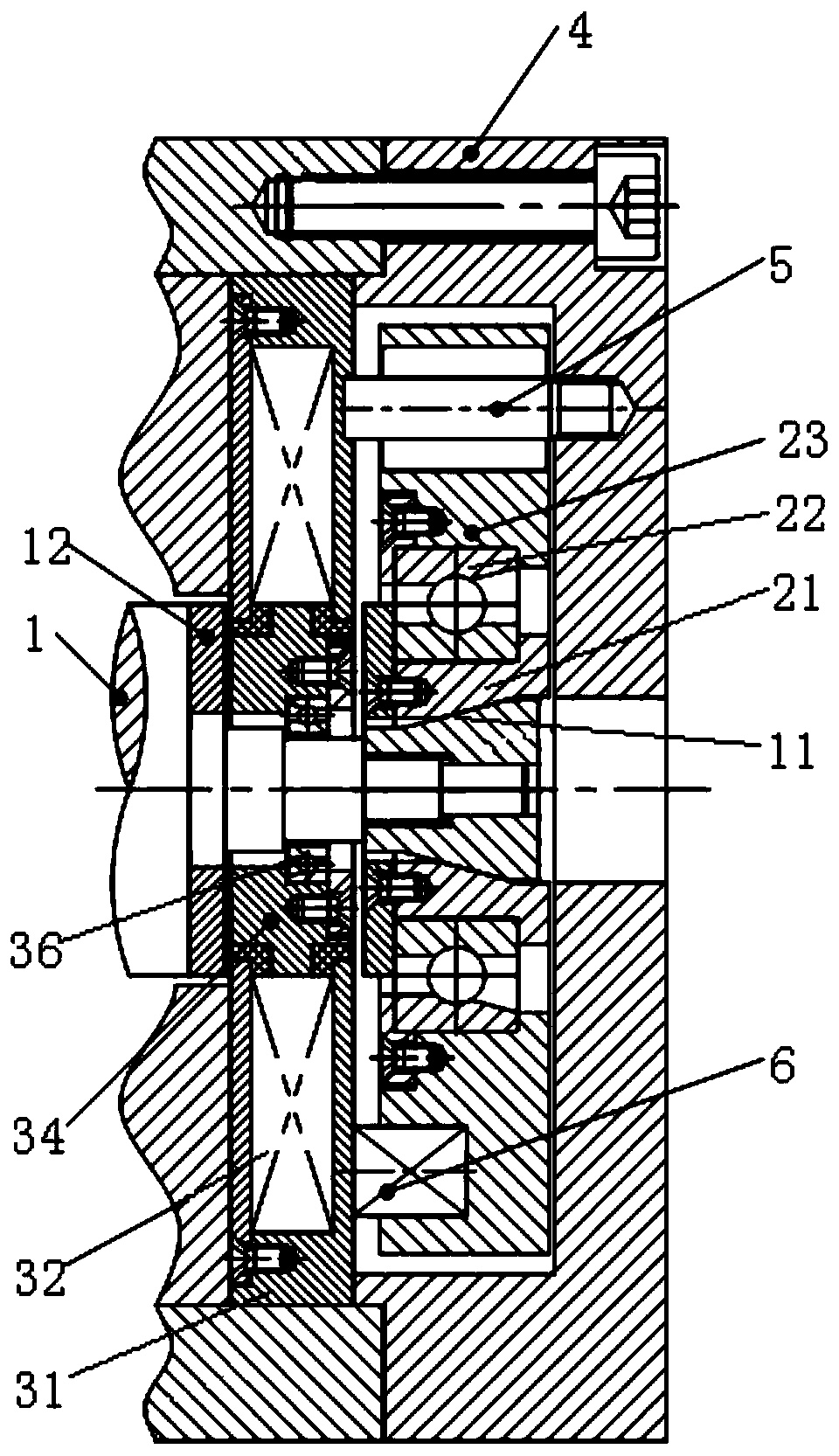
[0043] This embodiment is basically the same as the first embodiment, the only difference is: in this embodiment, the axial thrust disc 12 is located on the axial outer side of the support assembly 2, and the axial inner side of the axial thrust disc 12 abuts against the stepped surface of the rotor 1 , the axial outer side of the axial thrust plate 12 is limited by the limiting member 13 fixed on the rotor 1 . The tapered outer surface 11 in this embodiment is directly processed on the outer peripheral surface of the rotor 1 , and the outer diameter of the axially inner end of the tapered outer surface 11 is larger than the outer diameter of the axially outer end.


PUM


Abstract

The invention relates to the field of magnetic suspension bearing systems, in particular to an integrated electromagnetic protective bearing device. The integrated electromagnetic protective bearing device includes conical outer surfaces, two sets of supporting assemblies, two axial thrust discs and two sets of electromagnetic adsorption assemblies. The two conical outer surfaces are symmetricallyarranged at the two ends of a rotor; the two sets of supporting assemblies correspond to the two conical outer surfaces respectively, the inner peripheral surfaces of the supporting assemblies are inner conical surfaces matched with the conical outer surfaces, and the supporting assemblies can axially approach and rotationally support the conical outer surfaces; the two axial thrust discs are symmetrically arranged at the two ends of the rotor; and each electromagnetic adsorption assembly provides adsorption force for the corresponding supporting assembly and the corresponding axial thrust disc located at the same end, the rotor can normally rotate in a normal working state, the two axial thrust discs can ensure the axial balance of the rotor under the effect of the adsorption force, andin an emergency, the supporting assemblies axially approach and support the conical outer surfaces under the action of a reset element. The technical problems that a protective bearing device in the prior art has slow respond speed and a complex structure are solved.

Description

technical field [0001] The invention relates to the field of magnetic suspension bearing systems, in particular to an integrated electromagnetic protection bearing device. Background technique [0002] The magnetic suspension bearing system will lose the bearing capacity of the rotor in the event of an accidental power failure, so it is necessary to install a protective bearing device to provide temporary support for the rotor to prevent the high-speed rotating rotor from falling on the stator and cause damage to the stator. The safety of the magnetic levitation system. At present, the protective bearings used in the magnetic suspension system mostly use complex external mechanical mechanisms. Due to the complexity of the mechanism and the uncertainty of the accident, when the magnetic suspension bearing system is unexpectedly powered off, there will be phenomena such as the protection mechanism being stuck, and the bearing will be affected by the rotor. Large shocks and vi...

Claims


Application Information

Patent Timeline
Patent Type & Authority Applications(China)
IPC IPC(8): F16C32/04
CPCF16C32/0402F16C32/0442F16C32/0468F16C32/048F16C32/0493F16C2300/22
Inventor 俞成涛吉用秋孙月梅王秀英陈宇
Owner JIANGSU UNIV OF TECH
Learn More