Geological prospecting photoelectric measuring device
A photoelectric measurement and geological exploration technology, applied in the direction of measuring devices, optical devices, instruments, etc., can solve the problems that the depth or height of holes or protrusions cannot be directly measured, the progress of measurement work is not smooth, and the work efficiency is reduced. Solve the effects of poor practicability, inconvenient use, and strong practicability
- Summary
- Abstract
- Description
- Claims
- Application Information
AI Technical Summary
Problems solved by technology
Method used
Image

Examples
Embodiment Construction
[0030] The following will clearly and completely describe the technical solutions in the embodiments of the present invention with reference to the drawings in the embodiments of the present invention.
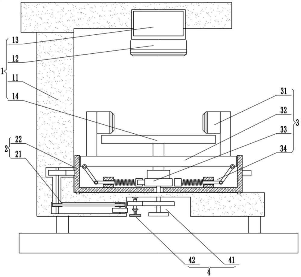
[0031] see Figure 1 to Figure 9 , the present embodiment provides a photoelectric measurement device for geological exploration, including a fixed measurement mechanism 1, the fixed measurement mechanism 1 includes a first camera group 12 and a bearing part 14, and also includes:
[0032] Activity measuring mechanism 3, described activity measuring mechanism 3 comprises movable platform 32; And several linkage assemblies 34 that are connected with movable platform 32, described movable platform 32 is provided with second camera group 31, and linkage assembly 34 one end is connected with eccentric Assembly 33, the bearing part 14 is connected with the eccentric assembly 33; and
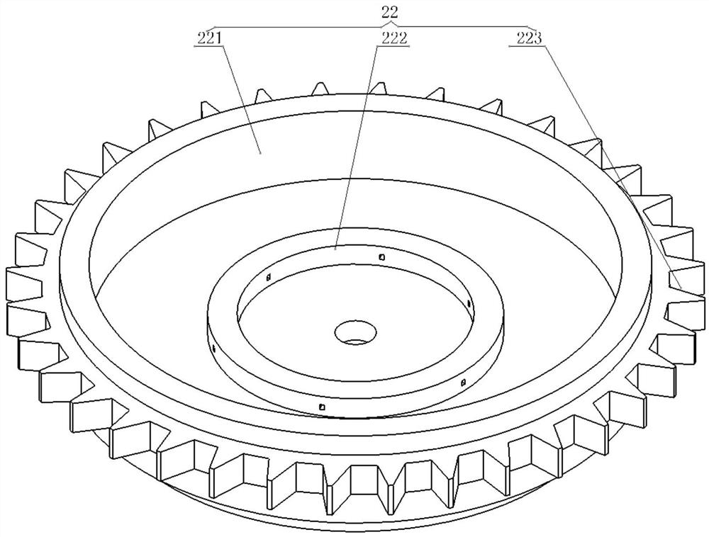
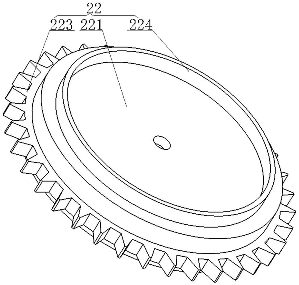
[0033] The rotating mechanism 2, the rotating mechanism 2 includes a rotating part 22 connected w...
PUM
 Abstract
Description
Claims
Application Information